|
STEP
|
INSPECTION
|
ACTION
|
|
|---|---|---|---|
|
1
|
DTC INSPECTION
Is the DTC displayed?
• B1319
|
Yes
|
Malfunction in the driver-side door latch switch system. Perform the inspection for DTC B1319. (See No.3 INTERIOR LIGHT STAYS ON-DOES NOT FADE OUT.)
|
|
No
|
Go to the next step.
|
||
|
2
|
DTC INSPECTION
Is the DTC displayed?
• B1309
|
Yes
|
Go to the next step.
|
|
No
|
Go to Step 6.
|
||
|
3
|
INSPECT DOOR LATCH PID
While opening and closing the driver-side door, use the display to inspect the GEM PID for the driver-side door latch switch.
Does the PID vary according to the lock/unlock status?
|
Yes
|
Go to the next step.
|
|
No
|
Malfunction in the driver-side door latch switch system
|
||
|
4
|
INSPECT DRIVER-SIDE DOOR LATCH SWITCH CIRCUIT FOR SHORT CIRCUIT
Verify that the driver-side door is closed completely.
Disconnect the GEM connector (26-pin).
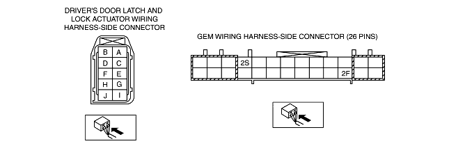
Measure the resistance between GEM connector terminal 2S (harness-side) and ground.
Is the resistance 10,000 ohms or more?
|
Yes
|
Go to Step 13.
|
|
No
|
Go to the next step.
|
||
|
5
|
INSPECT LOCK ACTUATOR FOR SHORT CIRCUIT
Disconnect the driver-side door latch and lock actuator connector.
Measure the resistance between driver-side door latch and lock actuator connector terminal D (harness-side) and ground.
Is the resistance 10,000 ohms or more?
|
Yes
|
Install a new driver-side door latch and lock actuator. (See FRONT DOOR LATCH AND LOCK ACTUATOR REMOVAL/INSTALLATION.)
Inspect the system for normal operation.
|
|
No
|
Repair the circuit.
Inspect the system for normal operation.
|
||
|
6
|
INSPECT DOOR LATCH OPERATION
While opening and closing the driver-side door, inspect the GEM PID for the driver-side door latch switch, using the display.
Does the PID vary normally according to the lock/unlock status?
|
Yes
|
Go to the next step.
|
|
No
|
Malfunction in the driver-side door latch switch system.
|
||
|
7
|
INSPECT DRIVER-SIDE DOOR LATCH SWITCH CIRCUIT FOR SHORT TO B+
Disconnect the GEM connector (26-pin).
Turn the ignition switch to the ON position.
Measure the voltage between GEM connector terminal 2S (harness-side) and ground.
Is there voltage?
|
Yes
|
Repair the suspected circuit.
Inspect the system for normal operation.
|
|
No
|
Go to the next step.
|
||
|
8
|
INSPECT DRIVER-SIDE DOOR LATCH SWITCH CIRCUIT FOR OPEN CIRCUIT
Measure the resistance between GEM connector terminal 2S (harness-side) and driver-side door latch and lock actuator connector terminal D (harness-side).
Is the resistance less than 5 ohms?
|
Yes
|
Go to the next step.
|
|
No
|
Repair the circuit.
Inspect the system for normal operation.
|
||
|
9
|
INSPECT ACTUATOR INTERNAL CIRCUIT
Connect the GEM connector (26-pin).
Open the driver-side door and verify that the latch is in the unlatch position.
While the door lock switch is in the lock position, measure the resistance between GEM connector terminal 2F (harness-side) and GEM connector terminal 2S (harness-side).
Is the resistance less than 5 ohms?
|
Yes
|
Go to Step 10.
|
|
No
|
Install a new driver-side door latch and lock actuator. (See FRONT DOOR LATCH AND LOCK ACTUATOR REMOVAL/INSTALLATION.)
Inspect the system for normal operation.
|
||
|
10
|
INSPECT GEM FOR NORMAL OPERATION
Disconnect the GEM connector.
Inspect for the following items:
• Corrosion
• Terminal separation
Connect all the connectors and verify that their positions are correct.
Operate the system and inspect for any malfunction.
Is there any malfunction?
|
Yes
|
Install a new GEM. (See GENERIC ELECTRONIC MODULE (GEM) REMOVAL/INSTALLATION.)
Clear the DTC and perform the DTC inspection.
|
|
No
|
Verify that the system operates normally at this stage.
The malfunction may result from loose connectors or corrosion.
Clear the DTC and perform the DTC inspection.
|
||
|
|
|||