|
STEP
|
INSPECTION
|
ACTION
|
|
|---|---|---|---|
|
1
|
INSPECT SUNROOF RELAY POWER SUPPLY CIRCUIT
Turn the ignition switch to the LOCK position.
Disconnect the sunroof relay connector.
Turn the ignition switch to the ON position.
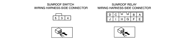
Measure the voltage between sunroof relay connector terminal G (harness-side) and ground.
Is the voltage 10 V or more?
|
Yes
|
Go to the next step.
|
|
No
|
Repair the supply circuit.
Inspect the system for normal operation.
|
||
|
2
|
INSPECT SUNROOF RELAY GROUND CIRCUIT FOR OPEN CIRCUIT
Turn the ignition switch to the LOCK position.
Measure the resistance between sunroof relay connector terminal E (harness-side) and ground.
Is the resistance less than 5 ohms?
|
Yes
|
Go to the next step.
|
|
No
|
Repair the circuit.
Inspect the system for normal operation.
|
||
|
3
|
INSPECT SUNROOF SWITCH
Connect the sunroof relay connector.
Disconnect the sunroof switch connector.
While pressing the sunroof switch rearward, measure the resistance between sunroof switch connector terminals 3 and 5 (part-side). While pressing the sunroof switch forward, measure the resistance between sunroof switch connector terminals 4 and 5 (part-side).
Is the resistance less than 5 ohms?
|
Yes
|
Go to the next step.
|
|
No
|
Install a new sunroof switch.
Inspect the system for normal operation.
|
||
|
4
|
INSPECT SUNROOF SWITCH POWER SUPPLY CIRCUIT FOR OPEN CIRCUIT
Disconnect the sunroof relay connector.
Connect the sunroof switch connector.
While pressing the sunroof switch rearward, measure the resistance between sunroof relay connector terminal C (harness-side) and ground.
Is the resistance less than 5 ohms while pressing the sunroof switch rearward?
|
Yes
|
Go to the next step.
|
|
No
|
Repair the circuit.
Inspect the system for normal operation.
|
||
|
5
|
INSPECT SUNROOF SWITCH POWER SUPPLY CIRCUIT FOR OPEN CIRCUIT
While pressing the sunroof switch forward, measure the resistance between sunroof relay connector terminal D (harness-side) and ground.
Is the resistance less than 5 ohms while pressing the sunroof switch forward?
|
Yes
|
Go to the next step.
|
|
No
|
Repair the circuit.
Inspect the system for normal operation.
|
||
|
6
|
INSPECT SUNROOF MOTOR POWER SUPPLY CIRCUIT
Connect the sunroof relay connector.
Turn the ignition switch to the ON position.
While pressing the sunroof switch rearward, measure the voltage between sunroof relay connector terminal B (harness-side) and ground.
Is the voltage 10 V or more?
|
Yes
|
Go to the next step.
|
|
No
|
Install a new sunroof relay. (See SUNROOF RELAY REMOVAL/INSTALLATION.)
Inspect the system for normal operation.
|
||
|
7
|
INSPECT SUNROOF MOTOR POWER SUPPLY
While pressing the sunroof switch forward, measure the voltage between sunroof relay connector A (harness-side) and ground.
Is the voltage 10 V or more?
|
Yes
|
Install a new sunroof motor. (See SUNROOF MOTOR REMOVAL/INSTALLATION.)
Inspect the system for normal operation.
|
|
No
|
Install a new sunroof relay. (See SUNROOF RELAY REMOVAL/INSTALLATION.)
Inspect the system for normal operation.
|
||
|
|
|||