Diagnostic Readout Box: Diagrams
Diagnostic Module
Terminal Layout Of Diagnostic Module:
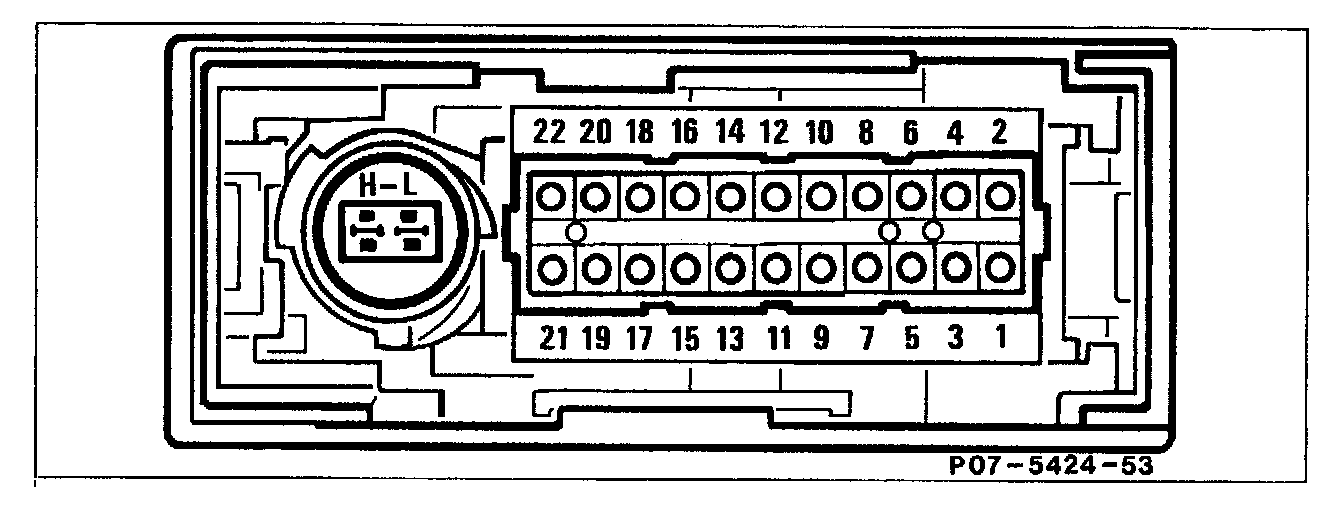
1 Main ground (behind instrument cluster, W1)
2 Ground bridge, coding
3 Voltage supply, circuit 87
4 Voltage supply, circuit 30 (fuse 9)
5 Not used
6 Diagnostic wire at diagnostic connector X11/21
7 Not used
8 Not used
9 "CHECK ENGINE" malfunction indicator lamp (MIL)
10 Main ground
(behind instrument cluster, W1)
11-17 Not used
18 Diagnostic module pressure sensor
19-21 Not used
22 Diagnostic module pressure sensor
H Dataline (+)
Controller Area Network
(Engine control module, electronic accelerator/cruise control/idle speed control module)
L Data line (-)
Controller Area Network
(Engine control module, electronic accelerator/cruise control/idle speed control module)