Control Module: Diagrams
Control Module Located In Module Box (Aluminum)
TCM (N15(1):
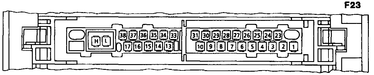
F23 Module box
1 Valve block control valve (Y3/1y2) (+)
2-9 Not used
10 Valve block control valve (Y3/1y2) (-)
13-17 Not used
23 Voltage supply circuit 87SA (from base module N16/1)
24 Not used
25 Diagnosis (output)
26 Not used
27 Kickdown switch (S16/6)
28 TR "D" contact switch (S16/9)
29 Transmission mode switch (S16/5)
30 Not used
31 Ground (W15)
33 Not used
34 Transmission overload protection switch (S65)
35-38 Not used
L CAN Data line (-)
H CAN Data line (+)
Control Module Located In Module Box (Plastic)
TCM (N15/1):
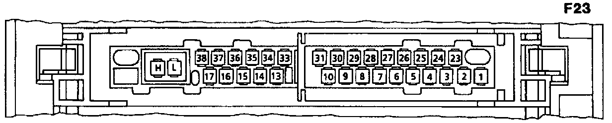
1 Valve block control valve (y3/1y2) (+)
2-9 Not used
10 Valve block control valve (Y3/1y2) (-)
12-17 Not used
23 Voltage supply circuit 87SA
24 Not used
25 Diagnosis (output)
26 Not used
27 Kickdown switch (S16/6)
28 TR "D" contact switch (S16/9)
29 Transmission mode switch (S16/5)
30 Ground (W15, W15/1)
33 Not used
34 Transmission overload protection switch (S65)
35-38 Not used
L CAN Data line (-)
H CAN Data line (+)