Fuel Delivery Module, Design
Fuel Delivery Module, Design
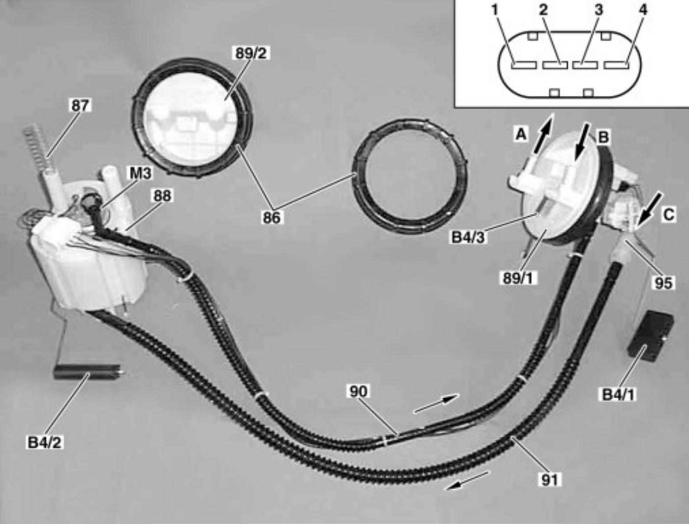
86 Union nut
87 Push spring
88 Fuel delivery module
89/1 Left closing plate
Pin 1 Fuel pump ground
Pin 2 Fuel gage sensor
Pin 3 Fuel gage sensor
Pin 4 Fuel pump circuit 87
89/2 Right closing plate
90 Fuel pressure line to connection A
91 Fuel connecting line
95 Suction spray pump
B4/1 Left fuel gage sensor
B4/2 Right fuel gage sensor
B4/3 Fuel tank pressure sensor (USA)
M3 Fuel pump (FP)
A to fuel filter with integrated fuel pressure regulator
B Return flow from fuel pressure regulator
C Fuel intake from left fuel chamber to delivery module
The fuel pump (M3), the right fuel level sensor (B4/2) and the splash bowl are integrated in the fuel delivery module:
- The fuel gage sensor is a lever-type sensor with sliding contacts (potentiometer)
- The fuel pump is a two-stage flow pump
- The splash bowl is a plastic housing and contains the following components