AZ82.70-P-0005-02V Retrofit Hands-Free System Wiring Harness
AZ82.70-P-0005-02V Retrofit Hands-Free System Wiring Harness
- with CODE (525) MB Audio 50 APS radio
- with CODE (527) COMAND APS (with navigation)
- except CODE (273) Telephone preinstallation for portable CTEL (non-networked) VDA wiring
1 Prepare the CAN (4) wiring harness.
Component Identification:

2 Connect the CAN (4) wiring harness to the ICANI box (2) with the ICANI connector (32), and then connect the handsfree connector (FSE) (7) to the free connection at the interface box for the handsfree system (3).
3 Connect the interface connector (33) to the interface box for the handsfree system (3).

4 Connect the ground from the CAN wiring harness to ground (right footwell (W15/1).

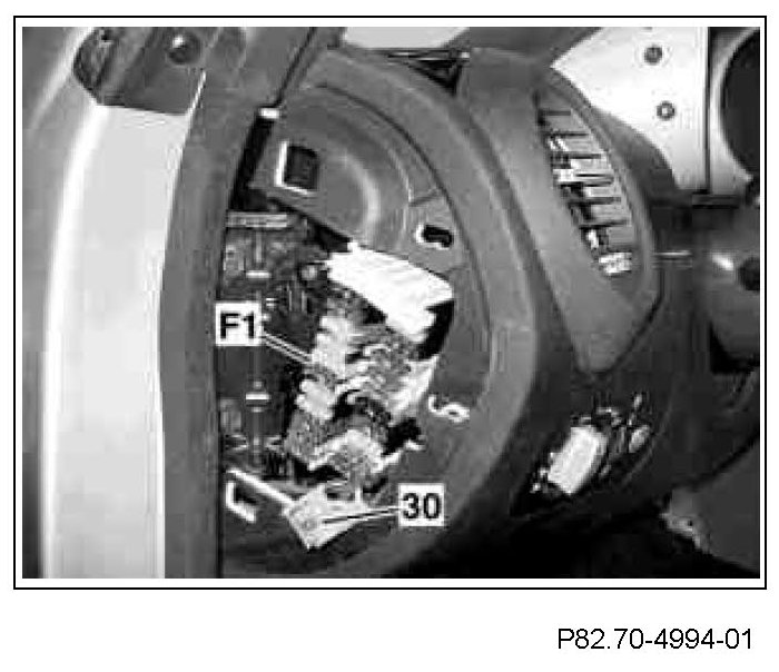
5 Route the voltage supply connector (30) to the left under the instrument panel and over to the fuse and relay box (F1), and then connect the fuse carrier to position 42. Insert a 7.5 A fuse in the fuse carrier.
6 Secure the connector line in place with adhesive felt.
7 Unplug the connector at the audio gateway control unit (N93/1), open the connector housing and remove the small 4-pin connector.
8 Remove the pink line, the brown line and the brown/red line from the connector.

9 Strap down the small 4-pin connector (arrow) with the remaining yellow line.
10 Insert the pink (rs) line removed in the step above into contact cavity 3 of the black 4- pin connector housing (sw) from the wiring harness (4) and then insert the 4-pin connector housing (sw) into the connector from the audio gateway control unit (N93/1). Close the connector and connect the audio gateway.
11 Insert the brown line (br) removed in the step above into contact cavity 2 and the brown/red line (br/rt) into contact cavity 1 of the blue connector housing for the CAN connection to the AGW (10).
Be sure to insert the brown (br) line into the cavity that has the gray/white line connected on the opposite side. Then insert the brown/red (br/rt) line into the cavity that has the gray line connected to it.

12 Route the microphone line with the microphone connector (MIC) to the right-side A-pillar and from there on up to the roof liner. Secure the line in place with adhesive felt.

13 Secure the microphone (6) to the overhead control panel (OCP) with double-sided adhesive tape (included in the parts kit) and then plug in the microphone connector (MIC).
Align microphone so that pickup opening points towards driver.

14 Position the outer part of the handsfree system speaker (21) on the lower right section of the A-pillar trim cover. Mark the hole for the speaker on the trim cover and then cut the required section.

15 Install the handsfree system speaker (21) and then plug in the speaker connector (SP).
