Backup Lamp: Description and Operation
GF82.10-P-3011SK Backup Lamp Actuation, Function
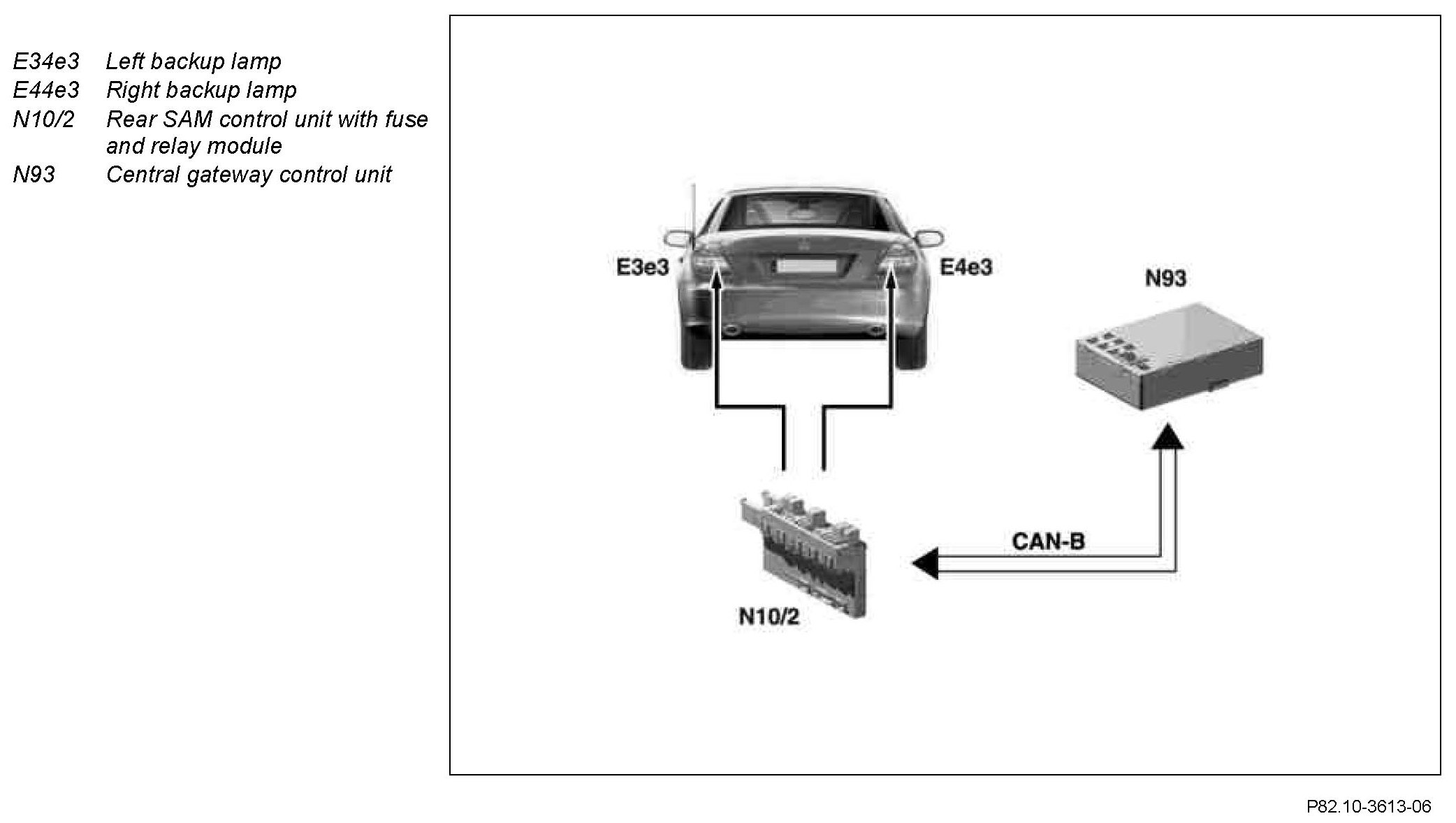
Component Identification:
Function requirements:
^ Circuit 15 ON
The request for switching on the left backup lamp (E3e3) and the right backup lamp (E4e3) is issued by the central gateway control unit (N93).
Automatic transmission:
The electronic selector lever module control unit (N15/5) supplies the signal to the Controller Area Network Bus Class C (engine compartment) (CAN-C). It is supplied by the central gateway control unit (N93) to the Controller Area Network Bus Class B (interior) (CAN-B). The rear SAM control unit with fuse and relay module (N10/2) receives this processed signal and discretely actuates the left backup lamp (E3e3) and the right backup lamp (E4e3).
To prevent the backup lamps to light up briefly when actuating the selector lever from "P" to "D" (via "R"), the message of the central gateway control unit (N93) is "filtered out" for t = 500 ms. If the message has timed-out, the taillamps are not actuated.
Manual transmission:
The reverse speed signal is read in by the driver-side SAM control unit with fuse and relay module (N10/1) via the backup lamp switch (S16/2) and supplied to the CAN-B. The central gateway control unit (N93) reads in this signal and generates a new message. The rear SAM control unit with fuse and relay module (N10/2) receives this processed signal and discretely actuates the left backup lamp (E3e3) and the right backup lamp (E4e3).
