0319
The injection valve output stage of cylinder 2 detects a line discontinuity. (P0202)
Possible cause:
- Y62y2 (Fuel injector cylinder 2)
- N10/1kI (Circuit 87 relay, engine)
- N10/1f43 (Fuse 43)
- Voltage supply via component Z7/38 (Circuit 87 M1i connector sleeve)
Affected functions:
- Engine diagnosis
- Engine running
-------------------------------------------------
Test 1: Check power supply of component N3/10 (ME-SFI [ME] control unit).
Test 2: Arrangement of fuses
Test 3: Power supply
Test 4: Check component Y62y2 (Fuel injector cylinder 2).
1. Check power supply of component N3/10 (ME-SFI [ME] control unit).
Test 1.1: Test voltage supply of circuit 87. ( Check using actual value )
Test 1.2: Test voltage supply of circuit 30.
Test 1.3: Test voltage supply of circuit 87.
Test 1.4: Test current consumption of component N10/1kR (Circuit 87 relay, engine).
Test 1.5: Test voltage supply of circuit 15.
1.1. Test voltage supply of circuit 87. ( Check using actual value )
Test prerequisite
- The voltage test at component G1 (Battery) is o.k.
- Ignition ON
Status of relevant actual value:
- Battery voltage:Warning! Communication with ECU required.
Specified value
- Battery voltage[11.0 ... 15.0] V
Question:Is the actual value o.k.?
YES
The actual value is okay.End of test
NO
The actual value is not o.k.Possible cause and remedy
- Test voltage supply of circuit 30.
- Test voltage supply of circuit 87.
1.2. Test voltage supply of circuit 30.
Connect socket box to component N3/10 (ME-SFI [ME] control unit).
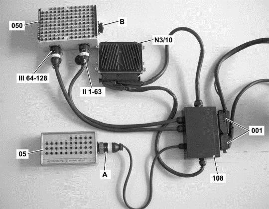
Figure legend
- A -ConnectionTest cable 35-pin socket box
- 001 -Sockets of component N3/10 (ME-SFI [ME] control unit)
- 05 -35-pin socket box
- 050 -126-pin socket box
- 108 -Test cable 266 589 01 63 00
- N3/10 (ME-SFI [ME] control unit)
- II 1-63ConnectionTest cable
- III 64-126ConnectionTest cable
Warning!
-
- Connection A of test cable 108 may NOT be connected to connection B of the 126-pin socket box (050).
Continue to test with button F2
Test voltage supply of circuit 30.
Test sequence
- Measure direct voltage with multimeter between sockets [ F.2 ] 98 and [ F.16 ] 112 of the 35-pole socket box tester.
- Switch on ignition.
Specified value
- Voltage[11.0...15.0] V
Question
- Is the measurement value OK?
YES
The measurement value is OK.End of test
NO
The measurement value is not OK.Possible cause and remedy
- F34f42 (Fuse 42)
- Lines
End of test

1.3. Test voltage supply of circuit 87.
Connect socket box to component N3/10 (ME-SFI [ME] control unit).
Figure legend
- A -ConnectionTest cable 35-pin socket box
- 001 -Sockets of component N3/10 (ME-SFI [ME] control unit)
- 05 -35-pin socket box
- 050 -126-pin socket box
- 108 -Test cable 266 589 01 63 00
- N3/10 (ME-SFI [ME] control unit)
- II 1-63ConnectionTest cable
- III 64-126ConnectionTest cable
Warning!
-
- Connection A of test cable 108 may NOT be connected to connection B of the 126-pin socket box (050).
Continue to test with button F2
Test voltage supply of circuit 87.
Test sequence
- Measure direct voltage with multimeter between sockets [ F.2 ] 98 and [F.3] 99 of the 126-pole socket box tester.
- Measure direct voltage with multimeter between sockets [ F.4 ] 100 and [ F.5 ] 101 of the 126-pole socket box tester.
- Measure direct voltage with multimeter between sockets [ F.6 ] 102 and [ F.5 ] 101 of the 126-pole socket box tester.
- Switch on ignition.
Specified value
- Voltage[11.0...15.0] V
Question
- Are the measurement values OK?
YES
The measurement values are OK.Further possible causes of fault
- Test voltage supply of circuit 30.
NO
The measurement values are not OK.Possible cause and remedy
- N10/1f43 (Fuse 43)
- N10/1f44 (Fuse 44)
- N10/1kI (Circuit 87 relay, engine)
- Lines
- N10/1 (Driver-side SAM control unit with fuse and relay module)
End of test

1.4. Test current consumption of component N10/1kR (Circuit 87 relay, engine).
Connect socket box to component N3/10 (ME-SFI [ME] control unit).
Figure legend
- A -ConnectionTest cable 35-pin socket box
- 001 -Sockets of component N3/10 (ME-SFI [ME] control unit)
- 05 -35-pin socket box
- 050 -126-pin socket box
- 108 -Test cable 266 589 01 63 00
- N3/10 (ME-SFI [ME] control unit)
- II 1-63ConnectionTest cable
- III 64-126ConnectionTest cable
Warning!
-
- Connection A of test cable 108 may NOT be connected to connection B of the 126-pin socket box (050).
Continue to test with button F2
Test current consumption of component N10/1kR (Circuit 87 relay, engine).
Test sequence
- Measure direct current with multimeter between sockets [F.4] 100 and [F.27] 123 of the 126-pole socket box tester.
- Switch on ignition.
Specified value
- Amperage[0.1...0.3] A
Question
- Is the measurement value OK?
YES
The test was okay.End of test
NO
The measurement value is not OK.Possible cause and remedy
- Lines to component N10/1kR (Circuit 87 relay, engine)
- N10/1kR (Circuit 87 relay, engine)
End of test
1.5. Test voltage supply of circuit 15.
Connect socket box to component N3/10 (ME-SFI [ME] control unit).
Figure legend
- A -ConnectionTest cable 35-pin socket box
- 001 -Sockets of component N3/10 (ME-SFI [ME] control unit)
- 05 -35-pin socket box
- 050 -126-pin socket box
- 108 -Test cable 266 589 01 63 00
- N3/10 (ME-SFI [ME] control unit)
- II 1-63ConnectionTest cable
- III 64-126ConnectionTest cable
Warning!
-
- Connection A of test cable 108 may NOT be connected to connection B of the 126-pin socket box (050).
Continue to test with button F2
Test voltage supply of circuit 15.
Test sequence
- Measure direct voltage with multimeter between sockets [ F.2 ] 98 and [ F.15 ] 111 of the 35-pole socket box tester.
- Switch on ignition.
Specified value
- Voltage[11.0...15.0] V
Question
- Is the measurement value OK?
YES
The measurement value is OK.End of test
NO
The measurement value is not OK.Possible cause and remedy
- N10/1f52 (Fuse 52)
- Lines
End of test
2. Arrangement of fuses
Figure legend/figure
- N10/1 (Driver-side SAM control unit with fuse and relay module)
Fuses
- FuseF43-F67
Relays
- I =N10/1kI (Circuit 87 relay, engine)
- K =N10/1kK (Circuit 87 relay, chassis)
- L =N10/1kL (Starter relay)
- M =N10/1kM (SEQ [ASG] pump control relay)
- N =N10/1kN (Circuit 15 relay)
- O =N10/1kO (FAN relay module)
- P =N10/1kP (Circuit 15R relay)
- R =N10/1kR (Air pump or oil cooler fan relay)
3. Power supply
Voltage supply via component Z7/38 (Circuit 87 M1i connector sleeve)
Possible cause and remedy
- Check voltage supply according to wiring diagram.
4. Check component Y62y2 (Fuel injector cylinder 2).
Test 4.1: Check component Y62y2 (Fuel injector cylinder 2).
4.1. Check component Y62y2 (Fuel injector cylinder 2).
Safety note
Warning!Risk of explosion, poisoning and injury!Fuels are highly inflammable and toxic if inhaled. Fuels may cause skin damage. fuel vapors are explosive, invisible and spread out at floor level, they are toxic if inhaled and produce giddiness and an anaesthetizing effect.Rules of conduct and protective measures
- Wear suitable protective clothing.
- Pay attention to national safety precautions and regulations.
- No fire, sparks, naked flames and smoking.
- Ensure the work place is adequately ventilated.
- Never drain or pour in fuels over assembly pits.
- Store drained fuel in a suitable and sealed vessel.
- Immediately eliminate any fuel which has flowed out.
First-aid measures
- Clean moistened skin with water and soap.
- Change moistened clothing as quickly as possible.
- If fuel gets into your eyes, rinse out your eyes immediately with water and contact a doctor if necessary.
Test 4.1.1: Test actuation of component Y62y2 (Fuel injector cylinder 2).
Test 4.1.2: Test signal voltage of component Y62y2 (Fuel injector cylinder 2).
Test 4.1.3: Check internal resistance of component Y62y2 (Fuel injector cylinder 2).
Test 4.1.4: Inspect component Y62y2 (Fuel injector cylinder 2) for leaks.
Test 4.1.5: Inspect operation and spray pattern of component Y62y2 (Fuel injector cylinder 2).
4.1.1. Test actuation of component Y62y2 (Fuel injector cylinder 2).
Test prerequisite
- Coolant temperature > 80° C
- Engine RUNNING
Warning!Communication with ECU required.
4.1.2. Test signal voltage of component Y62y2 (Fuel injector cylinder 2).
Figure legend
- A -ConnectionTest cable 35-pin socket box
- 001 -Sockets of component N3/10 (ME-SFI [ME] control unit)
- 05 -35-pin socket box
- 050 -126-pin socket box
- 108 -Test cable 266 589 01 63 00
- N3/10 (ME-SFI [ME] control unit)
- II 1-63ConnectionTest cable
- III 64-126ConnectionTest cable
Warning!
- Connection A of test cable 108 may NOT be connected to connection B of the 126-pin socket box (050).
Continue to test with button F2
Test sequence
- Switch off ignition.
- ConnectionMeasuring system
- Observe oscilloscope pattern between sockets [M.51] 51 and [F.3] 99 of the 126-pole socket box tester.
- Run engine.
Note
- Measuring system:Communication with ECU required
4.1.3. Check internal resistance of component Y62y2 (Fuel injector cylinder 2).
Figure legend
- A -ConnectionTest cable 35-pin socket box
- 001 -Sockets of component N3/10 (ME-SFI [ME] control unit)
- 05 -35-pin socket box
- 050 -126-pin socket box
- 108 -Test cable 266 589 01 63 00
- N3/10 (ME-SFI [ME] control unit)
- II 1-63ConnectionTest cable
- III 64-126ConnectionTest cable
Warning!
- Connection A of test cable 108 may NOT be connected to connection B of the 126-pin socket box (050).
Continue to test with button F2
Test sequence
- Switch off ignition.
- Connect socket box (126-pin) to component N3/10 (ME-SFI [ME] control unit).
- Measure resistance with multimeter between sockets [M.51] 51 and [F.3] 99 of the 126-pole socket box tester.
Specified value
- Resistor[11...17]ohms
Question
- Is the measurement value OK?
YES
The measurement value is OK.Note
- In the event of stored faults with a high fault frequency count or in the event of customer complaints, check lines and connectors for loose contact and corrosion..
NO
The measurement value is not OK.Test sequence
- Switch off ignition.
- Connect shop-made test cable set to component Y62y2 (Fuel injector cylinder 2).
- Measure resistance with multimeter between pins (Y62) 1 and (Y62) 2
Specified value
- Resistor[11...13]ohms
Question
- Is the measurement value OK?
YES
The measurement value is OK.Possible cause and remedy
- Lines to component Y62y2 (Fuel injector cylinder 2)
NO
The measurement value is not OK.Possible cause and remedy
- Y62y2 (Fuel injector cylinder 2)
4.1.4. Inspect component Y62y2 (Fuel injector cylinder 2) for leaks.
Figure legend
- A -ConnectionTest cable 35-pin socket box
- 001 -Sockets of component N3/10 (ME-SFI [ME] control unit)
- 05 -35-pin socket box
- 050 -126-pin socket box
- 108 -Test cable 266 589 01 63 00
- N3/10 (ME-SFI [ME] control unit)
- II 1-63ConnectionTest cable
- III 64-126ConnectionTest cable
Warning!
- Connection A of test cable 108 may NOT be connected to connection B of the 126-pin socket box (050).
Continue to test with button F2
Figure legend
- 055Measuring beakerY62 (Fuel injectors)
Test sequence
- Switch off ignition.
- Remove fuel rail together with component Y62y2 (Fuel injector cylinder 2).
- Bridge between sockets (F.4) 100 and (F.17) 113 of the 126-pole socket box tester.
- Switch on ignition.
Specified value
- Component Y62y2 (Fuel injector cylinder 2) must not drip.
Question
- Was the test o.k.?

YES
The test was okay.Further possible causes of fault
- Inspect operation and spray pattern of component Y62y2 (Fuel injector cylinder 2).
NO
The test was not okay.Possible cause and remedy
- Y62y2 (Fuel injector cylinder 2)
4.1.5. Inspect operation and spray pattern of component Y62y2 (Fuel injector cylinder 2).
Figure legend
- A -ConnectionTest cable 35-pin socket box
- 001 -Sockets of component N3/10 (ME-SFI [ME] control unit)
- 05 -35-pin socket box
- 050 -126-pin socket box
- 108 -Test cable 266 589 01 63 00
- N3/10 (ME-SFI [ME] control unit)
- II 1-63ConnectionTest cable
- III 64-126ConnectionTest cable
Warning!
- Connection A of test cable 108 may NOT be connected to connection B of the 126-pin socket box (050).
Continue to test with button F2
Figure legend(Shop-made tool)
- 1xClutch 140 545 35 28
- 2xContact spring 004 545 56 26
- 1xRed banana connector
- 1xBlack banana connector
- 2,2 mRed cable with diameter 1,5 mm(Pin 1)
- 2,2 mBrown cable with diameter 1,5 mm(Pin 2)
- 2 mInsulation sheathing with diameter 6 mm

Test sequence
- Switch off ignition.
- Remove fuel rail together with component Y62y2 (Fuel injector cylinder 2).
- Bridge between sockets (F.2) 98 and (F.17) 113 of the 126-pole socket box tester.
- Switch on ignition.
- Component M3 (Fuel pump) runs.
- Hold component Y62y2 (Fuel injector cylinder 2) in a vessel and briefly operate manually with shop-made test cable set at sockets 98 and 99 of the 126-pin socket box.
Specified value
- Fuel injectors should eject fuel uniformly.
Question
- Was the test o.k.?

YES
The test was okay. End of test
NO
The test was not okay.Possible cause and remedy
- Y62y2 (Fuel injector cylinder 2)
End of test