Part 1
Physical fill level fault: upper limit exceeded
Possible cause:
- A1 (Instrument cluster)
Affected functions:
- CAN Communication
-------------------------------------------------
Test 1: Engine compartment CAN test
Test 2: Check component A1 (Instrument cluster).
1. Engine compartment CAN test
Test 1.1: Engine compartment CAN test
1.1. Engine compartment CAN test
Test 1.1.1: Procedure in case of CAN faults
Test 1.1.2: Read current CAN configuration and CAN fault codes
Test 1.1.3: Further CAN test options
1.1.1. Procedure in case of CAN faults
Test 1.1.1.1: How do I quickly reach my goal?
Test 1.1.1.2: General test information
Test 1.1.1.3: General CAN fundamentals
Test 1.1.1.4: Possible aids and their usage
1.1.1.1. How do I quickly reach my goal?
How do I quickly reach my goal?First call up menu item 'Evaluation of CAN fault codes' in case of CAN timeout fault codes and communication errors.The resulting tests must be performed.Menu item 'Further CAN test options' should only be called up if the above-specified tests do not produce the desired result.Note:Menu item 'General test information' can be called up for an explanation of the different CAN fault types.
1.1.1.2. General test information
Notes on CAN fault codes:CAN timeout fault
- A CAN timeout fault code is set due to the absence of a CAN input signal.The cause of this may be not only the transmitter control unit, but also the CAN networking.
- For example:No CAN message was received from control unit A.
Bus OFF fault
- A Bus OFF fault code is set, when the control unit cannot send a certain amount of messages to the CAN bus or the messages are incomplete.The control unit then switches off for a short time from CAN bus.
- For example:CAN controller: CAN bus OFF
Functional CAN fault
- A functional CAN fault code is set because of an implausible CAN input signal.The cause of this is not the CAN networking, but the transmitter control unit or its sensors.
- For example:CAN signal 'A' from control unit B is implausible.
Notes on CAN faults that cannot be read out as fault codes.Bus wake-up event
- An event that wakes up the bus without reason is designated a bus wake-up event.
- The cause of this is not the CAN networking, but the transmitter control unit or its sensors.
- Further possible causes of fault:
- Magnetic fields caused by nearby high-voltage installations, railroad installations or power plants.
- Magnetic fields can radiate on to lines and control units in rare cases and cause undefined behavior in the control units.
- The special tool 'Star Diagnosis CANtool' can be used to log bus wake-up events, bus keepawake events and other signals.
Bus keepawake event
- When a control unit keeps communication on the bus awake without reason, this is designated a bus keepawake event.
- The cause of this is not the CAN networking, but the transmitter control unit or its sensors.
- Further possible causes of fault:
- Magnetic fields caused by nearby high-voltage installations, railroad installations or power plants.
- Magnetic fields can radiate on to lines and control units in rare cases and cause undefined behavior in the control units.
- The special tool 'Star Diagnosis CANtool' can be used to log bus wake-up events, bus keepawake events and other signals.
1.1.1.2. No further information available.
1.1.1.3. General CAN fundamentals
Test 1.1.1.3.1: Low-Speed CAN (83,3 kBit/s)
Test 1.1.1.3.2: High-Speed CAN (125 kBit/s , 500 kBit/s)
1.1.1.3.1. Low-Speed CAN (83,3 kBit/s)
General CAN fundamentals
Low-Speed CAN (83,3 kBit/s)
- 83,3 kBit/s : For example:Interior CAN busSeries 211
- This CAN bus enables single-wire mode.
- 'Single-wire mode' means that fault-free communication between the control units is still possible even if one of the two CAN lines fails.
- This CAN bus does not require external terminating resistors.
Legend and description for figure 1CAN-H: CAN bus HighCAN-L: CAN bus LowECU 1 ... n: Control unit 1 ... nLegend and description for figure 2U 1: Specification approx. 3,6 voltsU 2: Specification approx. 0 voltsU 3: Specification approx. 2,5 voltsU 4: Specification approx. 1,4 voltsU 5: Specification approx. 5 voltsContinue with button F2


1.1.1.3.1. No further information available.
1.1.1.3.2. High-Speed CAN (125 kBit/s , 500 kBit/s)
General CAN fundamentals
High-Speed CAN (125 kBit/s , 500 kBit/s)
- 125 kBit/s : Interior CAN busSeries 221
- 125 kBit/s : Telematic CAN busSeries 221
- 500 kBit/s : For example:Drive train CAN bus
- 500 kBit/s : For example:Diagnostic CAN-Bus
- This CAN bus does not permit single-wire mode.
- This means that both CAN lines are always required for fault-free communication between the control units.
- This CAN bus requires external terminating resistors.
- The terminating resistors can be located in control units or voltage distributors depending on the CAN bus.
Legend and description for figure 1CAN-H: CAN bus HighCAN-L: CAN bus LowECU 1 ... n: Control unit 1 ... nCAN terminating resistor ( Example: 120ohms)Legend and description for figure 2U 1: Specification approx. 3,6 voltsU 2: Specification approx. 2,5 voltsU 3: Specification approx. 1,4 voltsContinue with button F2


1.1.1.3.2. No further information available.
1.1.1.4. Possible aids and their usage
Evaluation of CAN fault codes
- The control units present in the vehicle (actual configuration) are compared with the coding in control unit CGW (specified configuration).
- Filtering and evaluation of all CAN timeout fault codes present in the vehicleThe result of the evaluation leads to the required test steps.
Multimeter
- Aids for voltage and resistance measurement in menu item 'Measurements with multimeter on CAN network'
Measuring system
- Aid for graphic representation of CAN signal and voltage levels
- The specified characteristics shown in Measurement Technology are used to recognize changed CAN voltage levels, which can be caused by faulty CAN components.
- Possible procedure: Disconnect and then reconnect the CAN bus subscribers at the voltage distributor one at a time.Compare the pass image with the actual image from the oscilloscope.
Star Diagnosis CANtool
- Aids for representation of actual values and identification of bus wake-up events and bus keepawake events
Continue with button F2
1.1.1.4. No further information available.
1.1.2. Read current CAN configuration and CAN fault codes
Warning!Communication with ECU required.
1.1.3. Further CAN test options
Test 1.1.3.1: Information to engine compartment CAN network
Test 1.1.3.2: Measurements with multimeter on CAN network
Test 1.1.3.3: Test with the aid of the measuring system
Test 1.1.3.4: Display CAN signals with the aid of the special tool 'Star Diagnosis CANtool'.
1.1.3.1. Information to engine compartment CAN network
Test 1.1.3.1.1: Arrangement diagramNOTESome of the control units listed are special equipment and not installed in every vehicle.
Test 1.1.3.1.2: Wiring diagram of CAN bus
1.1.3.1.1. Arrangement diagramNOTESome of the control units listed are special equipment and not installed in every vehicle.
Location diagram (with special equipment)
Figure legend
- A1 (Instrument cluster)
- A89 (DTR controller unit)
- N3/9 (CDI control unit)
- N3/10 (ME-SFI [ME] control unit)
- N15/3 (ETC [EGS] control unit)
- N15/5 (Electronic selector lever module control unit)
- N47-5 (ESP, SPS [PML] and BAS control unit)
- N51 (AIRmatic with ADS control module)
- N63/1 (DTR control module)
- N71 (Headlamp range adjustment control module)
- N73 (EIS [EZS] control unit)
- N80 (Steering column module)
- N93 (Central gateway control unit)
- N97 (Rear axle level control system control module)
- X11/4 (Diagnosis test connector)
- X30/5 (Left voltage distributor (CAN) connector)
- Installation point of plug connection X30/5 (Left voltage distributor (CAN) connector)
- Communication with ECU required

1.1.3.1.2. Wiring diagram of CAN bus
Note
- WIS is not available on this system.
- It is not possible to display the requested WIS document [ pe0019p2200da ].
- You can start WIS on another system and display the WIS document by entering the document number [ pe0019p2200da ] in the 'Contents' field.
1.1.3.1.2. No further information available.
1.1.3.2. Measurements with multimeter on CAN network
Test 1.1.3.2.1: Voltage supply of engine compartment CAN control modules
Test 1.1.3.2.2: Resistance test of engine compartment CAN
1.1.3.2.1. Voltage supply of engine compartment CAN control modules
Test 1.1.3.2.1.1: Check power supply at control unit A1 (Instrument cluster).
Test 1.1.3.2.1.2: Check power supply at control unit A89 (DTR controller unit).
Test 1.1.3.2.1.3: Check power supply at control unit N3/10 (ME-SFI [ME] control unit).
Test 1.1.3.2.1.4: Check power supply at control unit N15/3 (ETC [EGS] control unit).
Test 1.1.3.2.1.5: Check power supply at control unit N15/5 (Electronic selector lever module control unit).
Test 1.1.3.2.1.6: Check power supply at control unit N15/6 (Sprintshift control module).
Test 1.1.3.2.1.7: Check power supply at control unit N47-5 (ESP, SPS [PML] and BAS control unit).
Test 1.1.3.2.1.8: Check power supply at control unit N51 (AIRmatic with ADS control module).
Test 1.1.3.2.1.9: Check power supply at control unit N63/1 (DTR control module).
Test 1.1.3.2.1.10: Check power supply at control unit N71 (Headlamp range adjustment control module).
Test 1.1.3.2.1.11: Check power supply at control unit N73 (EIS [EZS] control unit).
Test 1.1.3.2.1.12: Check power supply at control unit N80 (Steering column module).
Test 1.1.3.2.1.13: Check power supply at control unit Y3/8n4 (Fully integrated transmission control (VGS) control unit).
1.1.3.2.1.1. Check power supply at control unit A1 (Instrument cluster).
Test prerequisites
- The fuses are OK.
- The power supply of the control unit N10/1 (Front SAM control unit with fuse and relay module) is OK.
Test sequence
- Switch off ignition.
- Detach the socket at component A1 (Instrument cluster).
- Measure direct voltage with multimeter between sockets (A1) 1 and (A1) 6
- Measure direct voltage with multimeter between sockets (A1) 2 and (A1) 6
- Measure direct voltage with multimeter between sockets (A1) 3 and (A1) 6
- Switch on ignition.
Specified value
- Voltage [11.0...14.5] V
Question:Is the measurement value OK?
YES
The measurement value is OK.Possible cause and remedy
- Perform inspection of connector and of socket for bent pins and enlarged contacts.
- Control unit A1 (Instrument cluster)
End of test
NO
The measurement value is not OK.Possible cause and remedy
- Line between component A1 (Instrument cluster) and component N10/1 (Front SAM control unit with fuse and relay module)
- Lines between A1 (Instrument cluster) and W28/1 (Ground, left inner door sill)
- Perform inspection of connector and of socket for bent pins and enlarged contacts.
End of test
1.1.3.2.1.2. Check power supply at control unit A89 (DTR controller unit).
Check power supply at control unit A89 (DTR controller unit).
Figure legend
- A89 (DTR controller unit)
Test prerequisite
- The voltage test at component G1 (Battery) is o.k.
- Fuse 45 in component N10/1 (Driver-side SAM control unit with fuse and relay module) is o.k.
Test sequence
- Switch off ignition.
- Detach coupling at component A89 (DTR controller unit).
- 1.Measure direct voltage with multimeter between sockets 1 and 1.6
- Switch on ignition.
Specified value
- [11.0 ... 14.5] V
Question
- Is the value o.k.?

YES
Note
- In the event of stored faults with a high fault frequency count or in the event of customer complaints, check lines and connectors for loose contact and corrosion..
End of test
NO
The measured value is not within the specified value range.Possible cause and remedy
- Cables between component N10/1 (Driver-side SAM control unit with fuse and relay module) and control module A89 (DTR controller unit)
- Plug connection X11/36
1.1.3.2.1.3. Check power supply at control unit N3/10 (ME-SFI [ME] control unit).
Test 1.1.3.2.1.3.1: Test voltage supply of circuit 87. ( Check using actual value )
Test 1.1.3.2.1.3.2: Test voltage supply of circuit 30.
Test 1.1.3.2.1.3.3: Test current consumption of component N10/1kR (Circuit 87 relay, engine).
Test 1.1.3.2.1.3.4: Test voltage supply of circuit 15.
1.1.3.2.1.3.1. Test voltage supply of circuit 87. ( Check using actual value )
Test prerequisite
- The voltage test at component G1 (Battery) is o.k.
- Ignition ON
Status of relevant actual value:
- Battery voltage:Warning! Communication with ECU required.
Specified value
- Battery voltage[11.0 ... 15.0] V
Question:Is the actual value o.k.?
YES
The actual value is okay.End of test
NO
The actual value is not o.k.Possible cause and remedy
- Test voltage supply of circuit 30.
- Test voltage supply of circuit 87.
1.1.3.2.1.3.2. Test voltage supply of circuit 30.
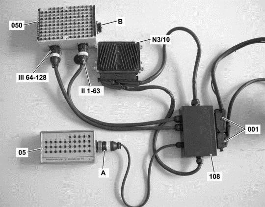
Connect socket box to component N3/10 (ME-SFI [ME] control unit).
Figure legend
- A -ConnectionTest cable 35-pin socket box
- 001 -Sockets of component N3/10 (ME-SFI [ME] control unit)
- 05 -35-pin socket box
- 050 -126-pin socket box
- 108 -Test cable 266 589 01 63 00
- N3/10 (ME-SFI [ME] control unit)
- II 1-63ConnectionTest cable
- III 64-126ConnectionTest cable
Warning!
-
- Connection A of test cable 108 may NOT be connected to connection B of the 126-pin socket box (050).
Continue to test with button F2
Test voltage supply of circuit 30.
Test sequence
- Measure direct voltage with multimeter between sockets [ F.2 ] 98 and [ F.16 ] 112 of the 35-pole socket box tester.
- Switch on ignition.
Specified value
- Voltage[11.0...15.0] V
Question
- Is the measurement value OK?
YES
The measurement value is OK.End of test
NO
The measurement value is not OK.Possible cause and remedy
- F34f42 (Fuse 42)
- Lines
End of test

1.1.3.2.1.3.3. Test current consumption of component N10/1kR (Circuit 87 relay, engine).
Connect socket box to component N3/10 (ME-SFI [ME] control unit).
Figure legend
- A -ConnectionTest cable 35-pin socket box
- 001 -Sockets of component N3/10 (ME-SFI [ME] control unit)
- 05 -35-pin socket box
- 050 -126-pin socket box
- 108 -Test cable 266 589 01 63 00
- N3/10 (ME-SFI [ME] control unit)
- II 1-63ConnectionTest cable
- III 64-126ConnectionTest cable
Warning!
-
- Connection A of test cable 108 may NOT be connected to connection B of the 126-pin socket box (050).
Continue to test with button F2
Test current consumption of component N10/1kR (Circuit 87 relay, engine).
Test sequence
- Measure direct current with multimeter between sockets [F.4] 100 and [F.27] 123 of the 126-pole socket box tester.
- Switch on ignition.
Specified value
- Amperage[0.1...0.3] A
Question
- Is the measurement value OK?
YES
The test was okay.End of test
NO
The measurement value is not OK.Possible cause and remedy
- Lines to component N10/1kR (Circuit 87 relay, engine)
- N10/1kR (Circuit 87 relay, engine)
End of test
1.1.3.2.1.3.4. Test voltage supply of circuit 15.
Connect socket box to component N3/10 (ME-SFI [ME] control unit).
Figure legend
- A -ConnectionTest cable 35-pin socket box
- 001 -Sockets of component N3/10 (ME-SFI [ME] control unit)
- 05 -35-pin socket box
- 050 -126-pin socket box
- 108 -Test cable 266 589 01 63 00
- N3/10 (ME-SFI [ME] control unit)
- II 1-63ConnectionTest cable
- III 64-126ConnectionTest cable
Warning!
-
- Connection A of test cable 108 may NOT be connected to connection B of the 126-pin socket box (050).
Continue to test with button F2
Test voltage supply of circuit 15.
Test sequence
- Measure direct voltage with multimeter between sockets [ F.2 ] 98 and [ F.15 ] 111 of the 35-pole socket box tester.
- Switch on ignition.
Specified value
- Voltage[11.0...15.0] V
Question
- Is the measurement value OK?
YES
The measurement value is OK.End of test
NO
The measurement value is not OK.Possible cause and remedy
- N10/1f52 (Fuse 52)
- Lines
End of test

1.1.3.2.1.4. Check power supply at control unit N15/3 (ETC [EGS] control unit).
Test 1.1.3.2.1.4.1: Guided test
1.1.3.2.1.4.1. Guided test
Operation number of operation texts and work units or standard texts and flat rates:27-0641Possible cause
- Battery has incorrect charge state or is faulty.
- Local undervoltage of component N15/3 (ETC [EGS] control unit)
Test sequence
- Erase fault memory.
Continue with button "F2"
Warning!Communication with ECU required.
1.1.3.2.1.5. Check power supply at control unit N15/5 (Electronic selector lever module control unit).
Operation number of operation texts and work units or standard texts and flat rates:27-0641Test sequence
- Switch off ignition.
- Disconnect connector at component N15/5 (Electronic selector lever module control unit).
- Switch on ignition.
- [A.2] Measure direct voltage with multimeter between 2 and 1 [A.1]
Status of relevant actual value:
- Supply voltage (tml. 15):Warning! Communication with ECU required.
Specified value
- Voltage[7.0...16.0] V
Question
- Is the measurement value OK?
YES
The measurement value is OK.Possible cause and remedy
- Replace component Floor-mounted shift.
End of test
NO
The measurement value is not OK.Possible cause and remedy
- Check fuse f55 (voltage supply from control unit ESM) in component N10/1 (Front SAM control unit with fuse and relay module).
- Check all affected plugs, connectors and electrical components for damage, loose contact, corrosion etc. and repair if necessary.
End of test
1.1.3.2.1.6. Check power supply at control unit N15/6 (Sprintshift control module).
Test voltage supply of circuit 30.
Operation number of operation texts and work units or standard texts and flat rates:26-0641Test sequence
- Switch off ignition.
- Connect socket box to component N15/6 (Sprintshift control module).
- Measure direct voltage with multimeter between sockets (B.36) 36 and (B.38) 38 of the 126-pole socket box tester.
- Switch on ignition.
Specified value
- Voltage[11.0...14.5] V
Question
- Are the measurement values OK?

YES
Test voltage supply of circuit 87.
Operation number of operation texts and work units or standard texts and flat rates:26-0641Test sequence
- Switch off ignition.
- Connect socket box to component N15/6 (Sprintshift control module).
- Measure direct voltage with multimeter between sockets (A.30) 30 and (A.29) 29 of the 126-pole socket box tester.
- Switch on ignition.
Specified value
- Voltage[11.0...14.5] V
Question
- Is the measurement value OK?
YES
The measurement value is OK.End of test
NO
The measurement value is not OK.Possible cause and remedy
- Line from component N10/1 (Front SAM control unit with fuse and relay module) to component N15/6 (Sprintshift control module)
End of test
NO
The measurement value is not OK.Possible cause and remedy
- Check fuse "f63" (voltage supply from control unit ASG) in component N10/1 (Front SAM control unit with fuse and relay module).
- Test cables
End of test

1.1.3.2.1.7. Check power supply at control unit N47-5 (ESP, SPS [PML] and BAS control unit).
Test 1.1.3.2.1.7.1: Test voltage of terminal 87 at control unit N47-5 (ESP, SPS [PML] and BAS control unit).
Test 1.1.3.2.1.7.2: Test of cable for voltage supply
Test 1.1.3.2.1.7.3: Test procedure ground cable
1.1.3.2.1.7.1. Test voltage of terminal 87 at control unit N47-5 (ESP, SPS [PML] and BAS control unit).
Test prerequisite
- Battery voltage is OK.
Test sequence
- Switch off ignition.
- Connect socket box.
- Switch on ignition.
- Measure direct voltage with multimeter between sockets (2.23) 57 and (2.14) 48 of the 126-pole socket box tester.
Specified value
- [11...14 V]
Question
- Is the measurement value OK?
YES
The measurement value is OK.Note
- In the event of stored faults with a high fault frequency count or in the event of customer complaints, check lines and connectors for loose contact and corrosion..
End of test
NO
The measurement value is not OK.Possible cause and remedy
- Lines to component N47-5 (ESP, SPS [PML] and BAS control unit)
- N10/1f47 (Fuse 47)
End of test
1.1.3.2.1.7.2. Test of cable for voltage supply
Test prerequisite
- Battery voltage is OK.
Test sequence
- Switch off ignition.
- Connect socket box.
- Switch on ignition.
- Measure direct voltage with multimeter between ground and socket (2.14) 48 of the 126-pole socket box tester.
Specified value
- [11...14 V]
Question
- Is the measurement value OK?
YES
The measurement value is OK.Note
- In the event of stored faults with a high fault frequency count or in the event of customer complaints, check lines and connectors for loose contact and corrosion..
End of test
NO
The measurement value is not OK.Possible cause and remedy
- Lines to component N47-5 (ESP, SPS [PML] and BAS control unit)
- N10/1f47 (Fuse 47)
End of test
1.1.3.2.1.7.3. Test procedure ground cable
Test prerequisite
- Battery voltage is OK.
Test sequence
- Switch off ignition.
- Connect socket box.
- WMeasure resistance with multimeter between 9 and (2.23) 57 of the 35-pole socket box tester.
Specified value
- [<1ohms]
Question
- Is the measurement value OK?
YES
The measurement value is OK.Note
- In the event of stored faults with a high fault frequency count or in the event of customer complaints, check lines and connectors for loose contact and corrosion..
End of test
NO
The measurement value is not OK.Possible cause and remedy
- Ground cable
- W9 (Ground (at front left headlamp unit))
End of test