Part 2
The engine off time has an implausible value. (P2610)
1.1.3.2.1.3. Test terminating resistor of CAN element in control module N3/10 (ME-SFI [ME] control unit).
Test terminating resistor of component N3/10 (ME-SFI [ME] control unit).
Test sequence
- Switch off ignition.
- Connect socket box to component N3/10 (ME-SFI [ME] control unit).
- Connector F is plugged in at control unit.
- Unplug the socket F from the wiring harness at the socket box.
- Measure resistance with multimeter between sockets (F.41) 11 and (F.54) 24 of the 35-pole socket box tester.
Specified value
- Resistor[115...125]ohms
Question
- Is the measurement value OK?
YES
The measurement value is OK.End of test
NO
The measurement value is not OK.Possible cause and remedy
- Control unit N3/10 (ME-SFI [ME] control unit)
End of test
1.1.3.2.2. Voltage supply of engine compartment CAN control modules
Test 1.1.3.2.2.1: Check power supply at control unit A1 (Instrument cluster).
Test 1.1.3.2.2.2: Check power supply at control unit A89 (DTR controller unit).
Test 1.1.3.2.2.3: Check power supply at control unit N3/10 (ME-SFI [ME] control unit).
Test 1.1.3.2.2.4: Check power supply at control unit N15/3 (ETC [EGS] control unit).
Test 1.1.3.2.2.5: Check power supply at control unit N15/5 (Electronic selector lever module control unit).
Test 1.1.3.2.2.6: Check power supply at control unit N15/6 (Sprintshift control module).
Test 1.1.3.2.2.7: Check power supply at control unit N47-5 (ESP, SPS [PML] and BAS control unit).
Test 1.1.3.2.2.8: Check power supply at control unit N51 (AIRmatic with ADS control module).
Test 1.1.3.2.2.9: Check power supply at control unit N63/1 (DTR control module).
Test 1.1.3.2.2.10: Check power supply at control unit N71 (Headlamp range adjustment control module).
Test 1.1.3.2.2.11: Check power supply at control unit N73 (EIS [EZS] control unit).
Test 1.1.3.2.2.12: Check power supply at control unit N80 (Steering column module).
Test 1.1.3.2.2.13: Check power supply at control unit Y3/8n4 (Fully integrated transmission control (VGS) control unit).
1.1.3.2.2.1. Check power supply at control unit A1 (Instrument cluster).
Test prerequisites
- The fuses are OK.
- The power supply of the control unit N10/1 (Front SAM control unit with fuse and relay module) is OK.
Test sequence
- Switch off ignition.
- Detach the socket at component A1 (Instrument cluster).
- Measure direct voltage with multimeter between sockets (A1) 1 and (A1) 6
- Measure direct voltage with multimeter between sockets (A1) 2 and (A1) 6
- Measure direct voltage with multimeter between sockets (A1) 3 and (A1) 6
- Switch on ignition.
Specified value
- Voltage [11.0...14.5] V
Question:Is the measurement value OK?
YES
The measurement value is OK.Possible cause and remedy
- Perform inspection of connector and of socket for bent pins and enlarged contacts.
- Control unit A1 (Instrument cluster)
End of test
NO
The measurement value is not OK.Possible cause and remedy
- Line between component A1 (Instrument cluster) and component N10/1 (Front SAM control unit with fuse and relay module)
- Lines between A1 (Instrument cluster) and W28/1 (Ground, left inner door sill)
- Perform inspection of connector and of socket for bent pins and enlarged contacts.
End of test
1.1.3.2.2.2. Check power supply at control unit A89 (DTR controller unit).
Check power supply at control unit A89 (DTR controller unit).
Figure legend
- A89 (DTR controller unit)
Test prerequisite
- The voltage test at component G1 (Battery) is o.k.
- Fuse 45 in component N10/1 (Driver-side SAM control unit with fuse and relay module) is o.k.
Test sequence
- Switch off ignition.
- Detach coupling at component A89 (DTR controller unit).
- 1.Measure direct voltage with multimeter between sockets 1 and 1.6
- Switch on ignition.
Specified value
- [11.0 ... 14.5] V
Question
- Is the value o.k.?

YES
Note
- In the event of stored faults with a high fault frequency count or in the event of customer complaints, check lines and connectors for loose contact and corrosion..
End of test
NO
The measured value is not within the specified value range.Possible cause and remedy
- Cables between component N10/1 (Driver-side SAM control unit with fuse and relay module) and control module A89 (DTR controller unit)
- Plug connection X11/36
1.1.3.2.2.3. Check power supply at control unit N3/10 (ME-SFI [ME] control unit).
Test 1.1.3.2.2.3.1: Test voltage supply of circuit 87. ( Check using actual value )
Test 1.1.3.2.2.3.2: Test voltage supply of circuit 30.
Test 1.1.3.2.2.3.3: Test current consumption of component N10/1kR (Circuit 87 relay, engine).
Test 1.1.3.2.2.3.4: Test voltage supply of circuit 15.
1.1.3.2.2.3.1. Test voltage supply of circuit 87. ( Check using actual value )
Test prerequisite
- The voltage test at component G1 (Battery) is o.k.
- Ignition ON
Status of relevant actual value:
- Battery voltage:Warning! Communication with ECU required.
Specified value
- Battery voltage[11.0 ... 15.0] V
Question:Is the actual value o.k.?
YES
The actual value is okay.End of test
NO
The actual value is not o.k.Possible cause and remedy
- Test voltage supply of circuit 30.
- Test voltage supply of circuit 87.
1.1.3.2.2.3.2. Test voltage supply of circuit 30.
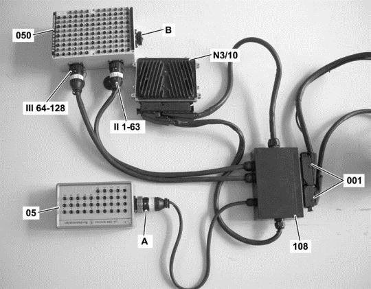
Connect socket box to component N3/10 (ME-SFI [ME] control unit).
Figure legend
- A -ConnectionTest cable 35-pin socket box
- 001 -Sockets of component N3/10 (ME-SFI [ME] control unit)
- 05 -35-pin socket box
- 050 -126-pin socket box
- 108 -Test cable 266 589 01 63 00
- N3/10 (ME-SFI [ME] control unit)
- II 1-63ConnectionTest cable
- III 64-126ConnectionTest cable
Warning!
-
- Connection A of test cable 108 may NOT be connected to connection B of the 126-pin socket box (050).
Continue to test with button F2
Test voltage supply of circuit 30.
Test sequence
- Measure direct voltage with multimeter between sockets [ F.2 ] 98 and [ F.16 ] 112 of the 35-pole socket box tester.
- Switch on ignition.
Specified value
- Voltage[11.0...15.0] V
Question
- Is the measurement value OK?
YES
The measurement value is OK.End of test
NO
The measurement value is not OK.Possible cause and remedy
- F34f42 (Fuse 42)
- Lines
End of test

1.1.3.2.2.3.3. Test current consumption of component N10/1kR (Circuit 87 relay, engine).
Connect socket box to component N3/10 (ME-SFI [ME] control unit).
Figure legend
- A -ConnectionTest cable 35-pin socket box
- 001 -Sockets of component N3/10 (ME-SFI [ME] control unit)
- 05 -35-pin socket box
- 050 -126-pin socket box
- 108 -Test cable 266 589 01 63 00
- N3/10 (ME-SFI [ME] control unit)
- II 1-63ConnectionTest cable
- III 64-126ConnectionTest cable
Warning!
-
- Connection A of test cable 108 may NOT be connected to connection B of the 126-pin socket box (050).
Continue to test with button F2
Test current consumption of component N10/1kR (Circuit 87 relay, engine).
Test sequence
- Measure direct current with multimeter between sockets [F.4] 100 and [F.27] 123 of the 126-pole socket box tester.
- Switch on ignition.
Specified value
- Amperage[0.1...0.3] A
Question
- Is the measurement value OK?
YES
The test was okay.End of test
NO
The measurement value is not OK.Possible cause and remedy
- Lines to component N10/1kR (Circuit 87 relay, engine)
- N10/1kR (Circuit 87 relay, engine)
End of test
1.1.3.2.2.3.4. Test voltage supply of circuit 15.
Connect socket box to component N3/10 (ME-SFI [ME] control unit).
Figure legend
- A -ConnectionTest cable 35-pin socket box
- 001 -Sockets of component N3/10 (ME-SFI [ME] control unit)
- 05 -35-pin socket box
- 050 -126-pin socket box
- 108 -Test cable 266 589 01 63 00
- N3/10 (ME-SFI [ME] control unit)
- II 1-63ConnectionTest cable
- III 64-126ConnectionTest cable
Warning!
-
- Connection A of test cable 108 may NOT be connected to connection B of the 126-pin socket box (050).
Continue to test with button F2
Test voltage supply of circuit 15.
Test sequence
- Measure direct voltage with multimeter between sockets [ F.2 ] 98 and [ F.15 ] 111 of the 35-pole socket box tester.
- Switch on ignition.
Specified value
- Voltage[11.0...15.0] V
Question
- Is the measurement value OK?
YES
The measurement value is OK.End of test
NO
The measurement value is not OK.Possible cause and remedy
- N10/1f52 (Fuse 52)
- Lines
End of test

1.1.3.2.2.4. Check power supply at control unit N15/3 (ETC [EGS] control unit).
Test 1.1.3.2.2.4.1: Guided test
1.1.3.2.2.4.1. Guided test
Operation number of operation texts and work units or standard texts and flat rates:27-0641Possible cause
- Battery has incorrect charge state or is faulty.
- Local undervoltage of component N15/3 (ETC [EGS] control unit)
Test sequence
- Erase fault memory.
Continue with button "F2"
Warning!Communication with ECU required.
1.1.3.2.2.5. Check power supply at control unit N15/5 (Electronic selector lever module control unit).
Operation number of operation texts and work units or standard texts and flat rates:27-0641Test sequence
- Switch off ignition.
- Disconnect connector at component N15/5 (Electronic selector lever module control unit).
- Switch on ignition.
- [A.2] Measure direct voltage with multimeter between 2 and 1 [A.1]
Status of relevant actual value:
- Supply voltage (tml. 15):Warning! Communication with ECU required.
Specified value
- Voltage[7.0...16.0] V
Question
- Is the measurement value OK?
YES
The measurement value is OK.Possible cause and remedy
- Replace component Floor-mounted shift.
End of test
NO
The measurement value is not OK.Possible cause and remedy
- Check fuse f55 (voltage supply from control unit ESM) in component N10/1 (Front SAM control unit with fuse and relay module).
- Check all affected plugs, connectors and electrical components for damage, loose contact, corrosion etc. and repair if necessary.
End of test
1.1.3.2.2.6. Check power supply at control unit N15/6 (Sprintshift control module).
Test voltage supply of circuit 30.
Operation number of operation texts and work units or standard texts and flat rates:26-0641Test sequence
- Switch off ignition.
- Connect socket box to component N15/6 (Sprintshift control module).
- Measure direct voltage with multimeter between sockets (B.36) 36 and (B.38) 38 of the 126-pole socket box tester.
- Switch on ignition.
Specified value
- Voltage[11.0...14.5] V
Question
- Are the measurement values OK?

YES
Test voltage supply of circuit 87.
Operation number of operation texts and work units or standard texts and flat rates:26-0641Test sequence
- Switch off ignition.
- Connect socket box to component N15/6 (Sprintshift control module).
- Measure direct voltage with multimeter between sockets (A.30) 30 and (A.29) 29 of the 126-pole socket box tester.
- Switch on ignition.
Specified value
- Voltage[11.0...14.5] V
Question
- Is the measurement value OK?
YES
The measurement value is OK.End of test
NO
The measurement value is not OK.Possible cause and remedy
- Line from component N10/1 (Front SAM control unit with fuse and relay module) to component N15/6 (Sprintshift control module)
End of test
NO
The measurement value is not OK.Possible cause and remedy
- Check fuse "f63" (voltage supply from control unit ASG) in component N10/1 (Front SAM control unit with fuse and relay module).
- Test cables
End of test

1.1.3.2.2.7. Check power supply at control unit N47-5 (ESP, SPS [PML] and BAS control unit).
Test 1.1.3.2.2.7.1: Test voltage of terminal 87 at control unit N47-5 (ESP, SPS [PML] and BAS control unit).
Test 1.1.3.2.2.7.2: Test of cable for voltage supply
Test 1.1.3.2.2.7.3: Test procedure ground cable
1.1.3.2.2.7.1. Test voltage of terminal 87 at control unit N47-5 (ESP, SPS [PML] and BAS control unit).
Test prerequisite
- Battery voltage is OK.
Test sequence
- Switch off ignition.
- Connect socket box.
- Switch on ignition.
- Measure direct voltage with multimeter between sockets (2.23) 57 and (2.14) 48 of the 126-pole socket box tester.
Specified value
- [11...14 V]
Question
- Is the measurement value OK?
YES
The measurement value is OK.Note
- In the event of stored faults with a high fault frequency count or in the event of customer complaints, check lines and connectors for loose contact and corrosion..
End of test
NO
The measurement value is not OK.Possible cause and remedy
- Lines to component N47-5 (ESP, SPS [PML] and BAS control unit)
- N10/1f47 (Fuse 47)
End of test
1.1.3.2.2.7.2. Test of cable for voltage supply
Test prerequisite
- Battery voltage is OK.
Test sequence
- Switch off ignition.
- Connect socket box.
- Switch on ignition.
- Measure direct voltage with multimeter between ground and socket (2.14) 48 of the 126-pole socket box tester.
Specified value
- [11...14 V]
Question
- Is the measurement value OK?
YES
The measurement value is OK.Note
- In the event of stored faults with a high fault frequency count or in the event of customer complaints, check lines and connectors for loose contact and corrosion..
End of test
NO
The measurement value is not OK.Possible cause and remedy
- Lines to component N47-5 (ESP, SPS [PML] and BAS control unit)
- N10/1f47 (Fuse 47)
End of test
1.1.3.2.2.7.3. Test procedure ground cable
Test prerequisite
- Battery voltage is OK.
Test sequence
- Switch off ignition.
- Connect socket box.
- WMeasure resistance with multimeter between 9 and (2.23) 57 of the 35-pole socket box tester.
Specified value
- [<1ohms]
Question
- Is the measurement value OK?
YES
The measurement value is OK.Note
- In the event of stored faults with a high fault frequency count or in the event of customer complaints, check lines and connectors for loose contact and corrosion..
End of test
NO
The measurement value is not OK.Possible cause and remedy
- Ground cable
- W9 (Ground (at front left headlamp unit))
End of test