Component Y16/2 (Heating system shutoff valve) has a short circuit to ground. (P0115)
Component Y16/2 (Heating system shutoff valve) has a short circuit to ground. (P0115)
Possible cause:
- Y16/2 (Heating system shutoff valve)
- N10/1kI (Circuit 87 relay, engine)
- N10/1f57 (Fuse 57)
Affected functions:
- Heating
-------------------------------------------------
Test 1: Check power supply of component N3/10 (ME-SFI [ME] control unit).
Test 2: Arrangement of fuses
Test 3: Check component Y16/2 (Heating system shutoff valve).
1. Check power supply of component N3/10 (ME-SFI [ME] control unit).
Test 1.1: Test voltage supply of circuit 87. ( Check using actual value )
Test 1.2: Test voltage supply of circuit 30.
Test 1.3: Test voltage supply of circuit 87.
Test 1.4: Test current consumption of component N10/1kR (Circuit 87 relay, engine).
Test 1.5: Test voltage supply of circuit 15.
1.1. Test voltage supply of circuit 87. ( Check using actual value )
Test prerequisite
- The voltage test at component G1 (Battery) is o.k.
- Ignition ON
Status of relevant actual value:
- Battery voltage:Warning! Communication with ECU required.
Specified value
- Battery voltage[11.0 ... 15.0] V
Question:Is the actual value o.k.?
YES
The actual value is okay.End of test
NO
The actual value is not o.k.Possible cause and remedy
- Test voltage supply of circuit 30.
- Test voltage supply of circuit 87.
1.2. Test voltage supply of circuit 30.
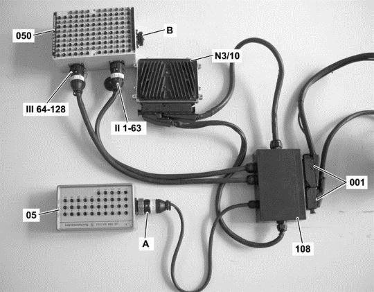
Connect socket box to component N3/10 (ME-SFI [ME] control unit).
Figure legend
- A -ConnectionTest cable 35-pin socket box
- 001 -Sockets of component N3/10 (ME-SFI [ME] control unit)
- 05 -35-pin socket box
- 050 -126-pin socket box
- 108 -Test cable 266 589 01 63 00
- N3/10 (ME-SFI [ME] control unit)
- II 1-63ConnectionTest cable
- III 64-126ConnectionTest cable
Warning!
-
- Connection A of test cable 108 may NOT be connected to connection B of the 126-pin socket box (050).
Continue to test with button F2
Test voltage supply of circuit 30.
Test sequence
- Measure direct voltage with multimeter between sockets [ F.2 ] 98 and [ F.16 ] 112 of the 35-pole socket box tester.
- Switch on ignition.
Specified value
- Voltage[11.0...15.0] V
Question
- Is the measurement value OK?
YES
The measurement value is OK.End of test
NO
The measurement value is not OK.Possible cause and remedy
- F34f42 (Fuse 42)
- Lines
End of test

1.3. Test voltage supply of circuit 87.
Connect socket box to component N3/10 (ME-SFI [ME] control unit).
Figure legend
- A -ConnectionTest cable 35-pin socket box
- 001 -Sockets of component N3/10 (ME-SFI [ME] control unit)
- 05 -35-pin socket box
- 050 -126-pin socket box
- 108 -Test cable 266 589 01 63 00
- N3/10 (ME-SFI [ME] control unit)
- II 1-63ConnectionTest cable
- III 64-126ConnectionTest cable
Warning!
-
- Connection A of test cable 108 may NOT be connected to connection B of the 126-pin socket box (050).
Continue to test with button F2
Test voltage supply of circuit 87.
Test sequence
- Measure direct voltage with multimeter between sockets [ F.2 ] 98 and [F.3] 99 of the 126-pole socket box tester.
- Measure direct voltage with multimeter between sockets [ F.4 ] 100 and [ F.5 ] 101 of the 126-pole socket box tester.
- Measure direct voltage with multimeter between sockets [ F.6 ] 102 and [ F.5 ] 101 of the 126-pole socket box tester.
- Switch on ignition.
Specified value
- Voltage[11.0...15.0] V
Question
- Are the measurement values OK?
YES
The measurement values are OK.Further possible causes of fault
- Test voltage supply of circuit 30.
NO
The measurement values are not OK.Possible cause and remedy
- N10/1f43 (Fuse 43)
- N10/1f44 (Fuse 44)
- N10/1kI (Circuit 87 relay, engine)
- Lines
- N10/1 (Driver-side SAM control unit with fuse and relay module)
End of test

1.4. Test current consumption of component N10/1kR (Circuit 87 relay, engine).
Connect socket box to component N3/10 (ME-SFI [ME] control unit).
Figure legend
- A -ConnectionTest cable 35-pin socket box
- 001 -Sockets of component N3/10 (ME-SFI [ME] control unit)
- 05 -35-pin socket box
- 050 -126-pin socket box
- 108 -Test cable 266 589 01 63 00
- N3/10 (ME-SFI [ME] control unit)
- II 1-63ConnectionTest cable
- III 64-126ConnectionTest cable
Warning!
-
- Connection A of test cable 108 may NOT be connected to connection B of the 126-pin socket box (050).
Continue to test with button F2
Test current consumption of component N10/1kR (Circuit 87 relay, engine).
Test sequence
- Measure direct current with multimeter between sockets [F.4] 100 and [F.27] 123 of the 126-pole socket box tester.
- Switch on ignition.
Specified value
- Amperage[0.1...0.3] A
Question
- Is the measurement value OK?
YES
The test was okay.End of test
NO
The measurement value is not OK.Possible cause and remedy
- Lines to component N10/1kR (Circuit 87 relay, engine)
- N10/1kR (Circuit 87 relay, engine)
End of test
1.5. Test voltage supply of circuit 15.
Connect socket box to component N3/10 (ME-SFI [ME] control unit).
Figure legend
- A -ConnectionTest cable 35-pin socket box
- 001 -Sockets of component N3/10 (ME-SFI [ME] control unit)
- 05 -35-pin socket box
- 050 -126-pin socket box
- 108 -Test cable 266 589 01 63 00
- N3/10 (ME-SFI [ME] control unit)
- II 1-63ConnectionTest cable
- III 64-126ConnectionTest cable
Warning!
-
- Connection A of test cable 108 may NOT be connected to connection B of the 126-pin socket box (050).
Continue to test with button F2
Test voltage supply of circuit 15.
Test sequence
- Measure direct voltage with multimeter between sockets [ F.2 ] 98 and [ F.15 ] 111 of the 35-pole socket box tester.
- Switch on ignition.
Specified value
- Voltage[11.0...15.0] V
Question
- Is the measurement value OK?
YES
The measurement value is OK.End of test
NO
The measurement value is not OK.Possible cause and remedy
- N10/1f52 (Fuse 52)
- Lines
End of test
2. Arrangement of fuses
Figure legend/figure
- N10/1 (Driver-side SAM control unit with fuse and relay module)
Fuses
- FuseF43-F67
Relays
- I =N10/1kI (Circuit 87 relay, engine)
- K =N10/1kK (Circuit 87 relay, chassis)
- L =N10/1kL (Starter relay)
- M =N10/1kM (SEQ [ASG] pump control relay)
- N =N10/1kN (Circuit 15 relay)
- O =N10/1kO (FAN relay module)
- P =N10/1kP (Circuit 15R relay)
- R =N10/1kR (Air pump or oil cooler fan relay)
3. Check component Y16/2 (Heating system shutoff valve).
Figure legend
- A -ConnectionTest cable 35-pin socket box
- 001 -Sockets of component N3/10 (ME-SFI [ME] control unit)
- 05 -35-pin socket box
- 050 -126-pin socket box
- 108 -Test cable 266 589 01 63 00
- N3/10 (ME-SFI [ME] control unit)
- II 1-63ConnectionTest cable
- III 64-126ConnectionTest cable
Warning!
- Connection A of test cable 108 may NOT be connected to connection B of the 126-pin socket box (050).
Continue to test with button F2
Test current consumption of component Y16/2 (Heating system shutoff valve).
Test sequence
- Switch off ignition.
- Connect socket box (126-pin) to component N3/10 (ME-SFI [ME] control unit).
- Measure direct current with multimeter between sockets [F.4] 100 and [M.71] 71 of the 126-pole socket box tester.
- Switch on ignition.
Specified value
- Amperage[0.7...1.2] A
Question
- Is the measurement value OK?
YES
The measurement value is OK.End of test
NO
The measurement value is not OK.Possible cause and remedy
- N10/1f57 (Fuse 57)
- N10/1kR (Circuit 87 relay, engine)
- Line between component N10/1 (Driver-side SAM control unit with fuse and relay module) and component Y16/2 (Heating system shutoff valve)
- Line between component N10/1 (Driver-side SAM control unit with fuse and relay module) and component N3/10 (ME-SFI [ME] control unit)
- Y16/2 (Heating system shutoff valve)
End of test