B6/4 (Left intake camshaft Hall sensor) : The time of the signal value change is implausible. (P0346)
B6/4 (Left intake camshaft Hall sensor) : The time of the signal value change is implausible. (P0346)
Possible cause:
- B6/4 (Left intake camshaft Hall sensor)
Affected functions:
- Engine diagnosis
- Engine output
-------------------------------------------------
Test 1: Check component B6/4 (Left intake camshaft Hall sensor).
1. Check component B6/4 (Left intake camshaft Hall sensor).
Test 1.1: Check component B6/4 (Left intake camshaft Hall sensor) using actual value.
Test 1.2: Check power supply of component B6/4 (Left intake camshaft Hall sensor).
Test 1.3: Check assignment of signals from Hall sensors 'Camshafts' and 'Crankshaft'.
1.1. Check component B6/4 (Left intake camshaft Hall sensor) using actual value.
Warning!Communication with ECU required.
1.2. Check power supply of component B6/4 (Left intake camshaft Hall sensor).
Test prerequisite
- The actual value is not o.k.
Test sequence
- Switch off ignition.
- Detach coupling at component B6/4 (Left intake camshaft Hall sensor).
- [ B6/4 ]Measure direct voltage with multimeter between sockets 1 and 3[ B6/4 ]
- Switch on ignition.
Specified value
- Voltage[11.0...15.0] V
Question
- Is the measurement value OK?
YES
The measurement value is OK.Further possible causes of fault
- Signal wire
- B6/4 (Left intake camshaft Hall sensor)
End of test
NO
The measurement value is not OK.Possible cause and remedy
- N10/1f43 (Fuse 43)
- N10/1kR (Circuit 87 relay, engine)
- Lines to component B6/4 (Left intake camshaft Hall sensor)
End of test
1.3. Check assignment of signals from Hall sensors 'Camshafts' and 'Crankshaft'.
Check assignment of signals from Hall sensors 'Camshafts' and 'Crankshaft'.
Figure legend
- A -ConnectionTest cable 35-pin socket box
- 001 -Sockets of component N3/10 (ME-SFI [ME] control unit)
- 05 -35-pin socket box
- 050 -126-pin socket box
- 108 -Test cable 266 589 01 63 00
- N3/10 (ME-SFI [ME] control unit)
- II 1-63ConnectionTest cable
- III 64-126ConnectionTest cable
Warning!
- Connection A of test cable 108 may NOT be connected to connection B of the 126-pin socket box (050).
Continue to test with button F2
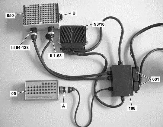
Figure legend
- 1Signal from component B6/5 (Right intake camshaft Hall sensor)
- 2Signal from component B6/7 (Right exhaust camshaft Hall sensor)
- 3Signal from component B6/4 (Left intake camshaft Hall sensor)
- 4Signal from component B6/6 (Left exhaust camshaft Hall sensor)
- 5Signal from component B70 (Crankshaft Hall sensor)
Test prerequisite
- Voltage supply is o.k.
Test sequence
- Switch off ignition.
- Connect socket box (126-pin) to component N3/10 (ME-SFI [ME] control unit).
- ConnectionMeasuring system
- Component B6/5 (Right intake camshaft Hall sensor):(A7) Observe oscilloscope pattern between sockets [M16] 16 and [M.57] 57 of the 126-pole socket box tester. (A.1)
- Component B6/7 (Right exhaust camshaft Hall sensor):(A7) Observe oscilloscope pattern between sockets [M16] 16 and [M.10] 10 of the 126-pole socket box tester. (A.2)
- Component B6/4 (Left intake camshaft Hall sensor):(A7) Observe oscilloscope pattern between sockets [M16] 16 and [M.56] 56 of the 126-pole socket box tester. (A.3)
- Component B6/6 (Left exhaust camshaft Hall sensor):(A7) Observe oscilloscope pattern between sockets [M16] 16 and [M.34] 34 of the 126-pole socket box tester. (A.4)
- Component B70 (Crankshaft Hall sensor):(A7) Observe oscilloscope pattern between sockets [M16] 16 and [M.81] 81 of the 126-pole socket box tester. (A5)
- Start engine.
- Enter the settings as shown in the right-hand diagram.
Specified value
- Measuring system
Note
- Measuring system:Communication with ECU required

