Expansion Block/Orifice Tube: Service and Repair
Spring Lock Coupling Disconnect Tool Set:

SPECIAL SERVICE TOOL(S) REQUIRED
REMOVAL
The A/C evaporator core orifice is located in the condenser to evaporator tube. The configuration of this condenser to evaporator tube is slightly different if the vehicle is equipped with an auxiliary rear air conditioning/heater system, but the A/C evaporator core orifice is still housed within it.
1. Discharge and recover the refrigerant from the A/C system.
2. Drain the engine coolant to a level below that of the water thermostat.
3. To gain access to the condenser to evaporator tube, remove the upper radiator hose clamps, upper radiator hose bracket, and upper radiator hose.
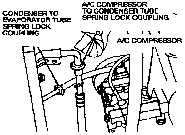
4. Use A/C Spring Lock Coupling Disconnect Tool Set T84L-19623-B to disconnect the condenser to evaporator tube spring lock coupling at the A/C condenser core outlet.
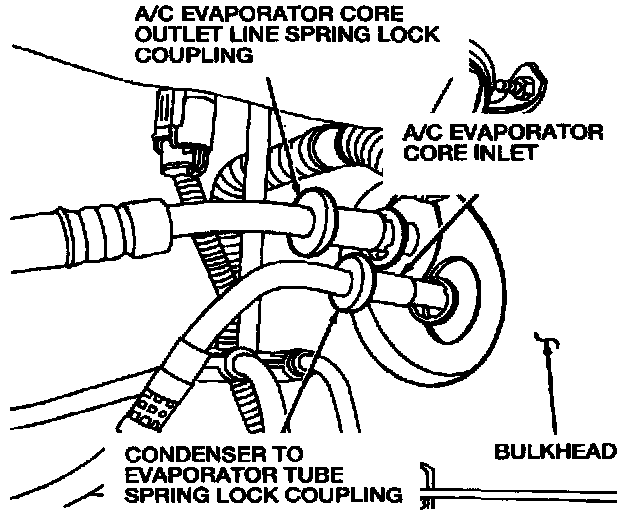
5. Use A/C Spring Lock Coupling Disconnect Tool Set T84L-19623-B to disconnect the condenser to evaporator tube at the A/C evaporator core inlet line spring lock coupling near the bulkhead.
6. Remove the A/C condenser inlet tube bracket screw and remove the condenser to evaporator tube (with the A/C evaporator core orifice) from the vehicle.
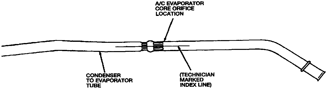
7. Locate the A/C evaporator core orifice by the indentation in the condenser to evaporator tube. Mark an index line on the condenser to evaporator tube to ensure proper position during assembly of the condenser to evaporator tube and orifice tube kit.
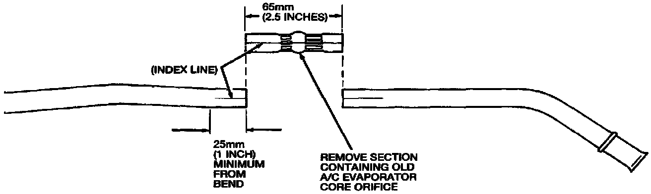
8. Cut a 65 mm (2.5 inches) section of the condenser to evaporator tube at the A/C evaporator core orifice location and remove the A/C evaporator core orifice.
CAUTION: Do not cut the section of the condenser to evaporator tube closer than 25 mm (1 inch) from the start of the bend.
INSTALLATION
1. Flush the two pieces of the condenser to evaporator tube to remove any contaminants.
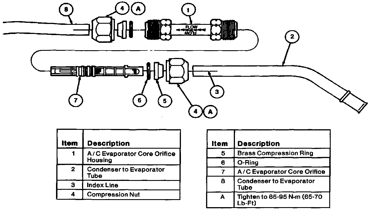
2. Install the A/C evaporator core orifice kit (E5VY-19D695-A) onto the condenser to evaporator tube as follows:
a. Install the compression nuts onto the two halves of the condenser to evaporator tube.
b. Install the brass compression rings onto the condenser to evaporator tube halves. Slide the brass compression rings so they fit into the compression nuts.
NOTE: Install the brass compression rings with the tapered ends toward the compression nut.
c. Lubricate the O-rings with clean refrigerant oil and then install them onto the condenser to evaporator tube halves behind the brass compression rings.
d. Install the A/C evaporator core orifice into the inlet side of the condenser to evaporator tube.
e. Install the A/C evaporator core orifice housing over the A/C evaporator core orifice and finger tighten the housing nut to the compression nut.
NOTE: The A/C evaporator core orifice housing must be installed with the flow direction arrows pointing toward the evaporator end of the condenser to evaporator tube.
f. Install the A/C evaporator core orifice housing onto the evaporator end of the condenser to evaporator tube and finger tighten the housing nut to the compression nut.
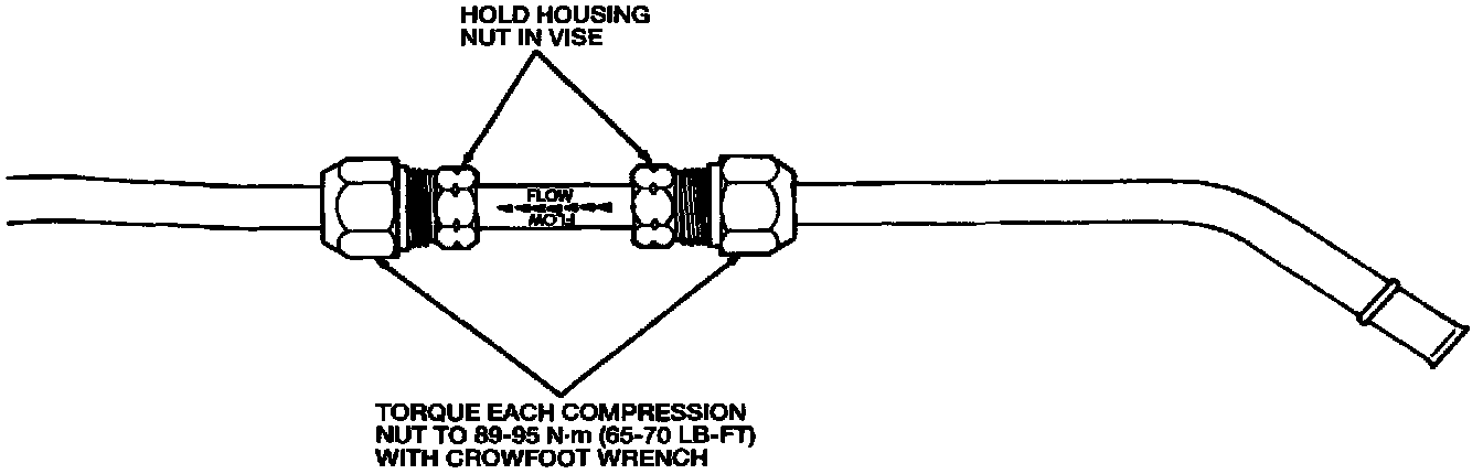
g. Place the housing nut in a vise. Use a crow foot wrench to tighten the compression nuts to 89-95 N.m (65-70 lb-ft).
NOTE: Ensure that the index line marked on the condenser to evaporator tube halves during removal line up prior to tightening the compression nuts.
3. Position the condenser to evaporator tube in the vehicle. Install the A/C condenser inlet tube bracket screw.
4. Connect the condenser to evaporator tube at the spring lock coupling near the bulkhead.
5. Connect the condenser to evaporator tube at the A/C condenser core spring lock coupling.
6. Install the upper radiator hose. Tighten the two upper radiator hose clamps to 19-23 N.m (14-17 lb-ft). Tighten the upper radiator hose to engine hose clamp bolt to 46-65 N.m (34-48 lb-ft).
7. Refill the engine coolant system.
8. Evacuate and charge the A/C system.
9. Leak test the A/C system.