Heater Core Case: Service and Repair
Heater Case
Removal
1. Drain the engine coolant.
2. Disconnect the battery ground cable (14301).
3. Disconnect the heater water hoses (18472) from the heater core (18476) at the bulkhead.
4. Remove the instrument panel lower center panel (04494). Service and Repair
5. Remove the glove compartment and LH instrument panel lower cover(044Lg7). Service and Repair
6. Remove the instrument panel ash receptacle (04810).
7. Remove the two upper center instrument panel finish panel screws and the two lower center instrument panel finish panel screws.
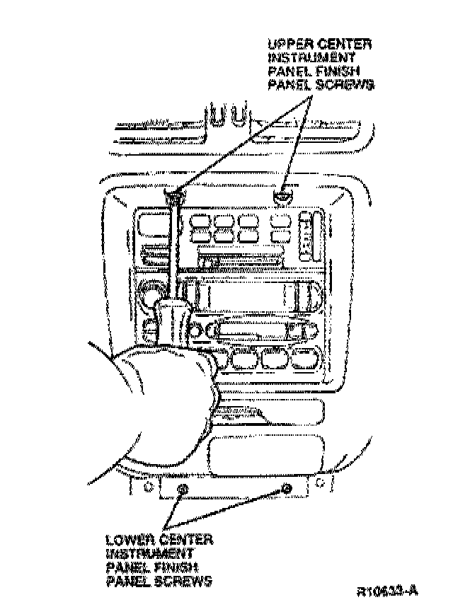
8. Remove the center instrument panel finish panel (044D70) and disconnect the cigar lighter socket and cigar lighter illumination lamp electrical connectors.
9. Remove the four radio chassis bracket screws and pull the radio chassis (18806) and climate control assembly from the instrument panel (04320). Disconnect the radio chassis electrical connectors, the antenna lead, the three climate control electrical connectors and remove the radio chassis and climate control assembly.
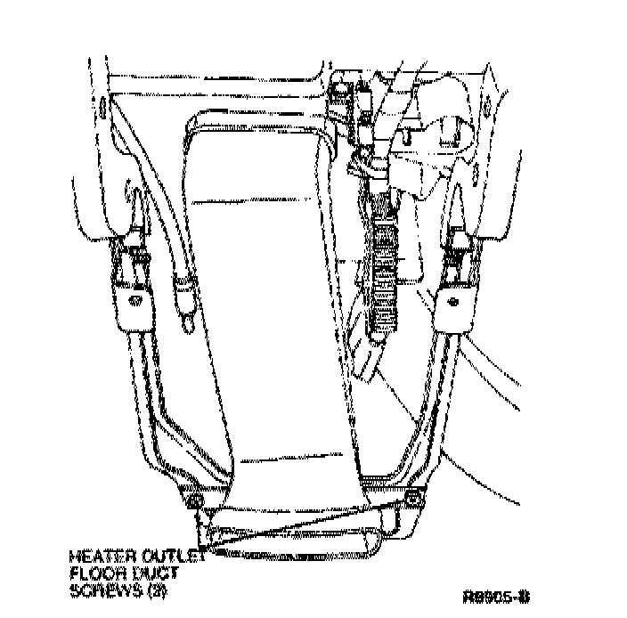
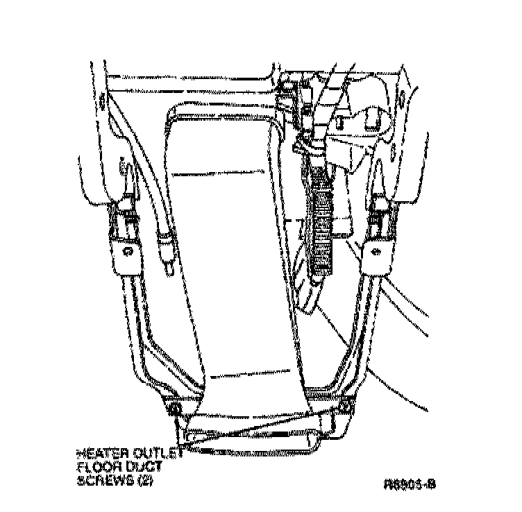
10. Remove the two heater outlet floor duct screws. Remove the heater outlet floor duct (18C433).
11. Remove the four RH instrument panel lower reinforcement bolts and the RH instrument panel lower reinforcement (045F08), then the four LH instrument panel lower reinforcement and the LH instrument panel lower reinforcement.
12. Remove the anti-lock brake control module (2B373). Antilock Brakes / Traction Control Systems
13. If equipped, remove the speed control amplifier. Fuel Delivery and Air Induction
14. Remove the electronic door lock control processor (14B001). Locks
15. Remove the passive restraint control module. Restraints and Safety Systems
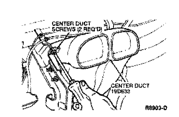
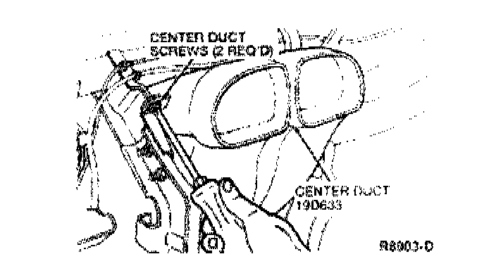
16. Remove the two center duct screws and remove the center duct (19D633).
17. Remove the two ground wire bolts.
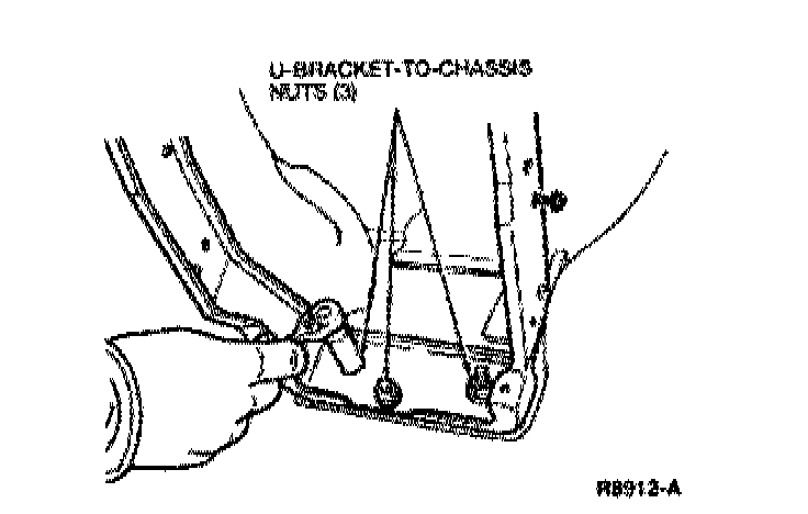
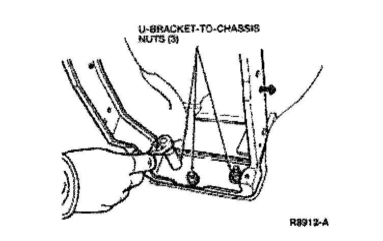
18. Remove the three U-bracket-to-chassis nuts.
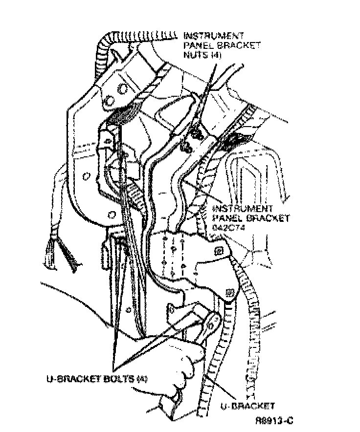
19. Remove the four U-bracket boits and remove the U-bracket.
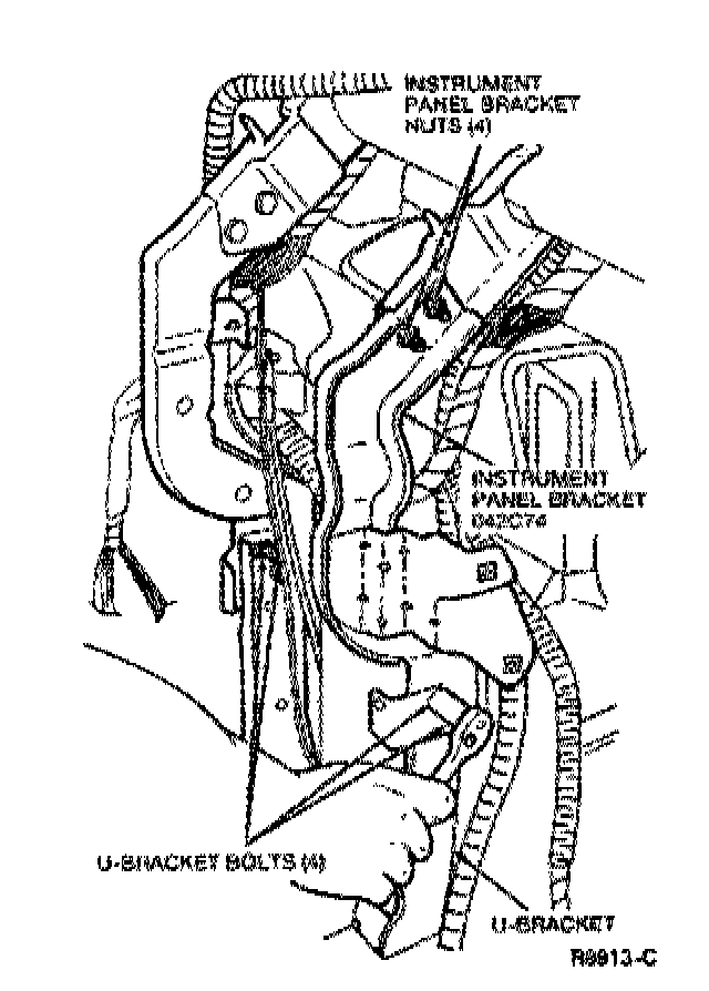
20. Remove the two RH and the two LH instrument panel bracket bolts and remove the instrument panel brackets (042C74).
21. Remove the RH inner duct.
22. Remove the LH inner duct.
23. Remove the two accelerator pedal and shaft bolts and then the accelerator pedal and shaft (9725).
24. Remove the accelerator pedal stop screw and then the accelerator pedal stop (9816).
25. Remove the heater outlet duct screw and remove the heater outlet duct.
26. Remove the temperature blend/panel bypass door actuator motor.
Service and Repair
27. Remove the panel/floor/defrost door actuator motor. Service and Repair
28. Remove the three A/C evaporator register duct screws and remove the A/C evaporator register duct.
29. NOTE:The A/C evaporatoriblower motor assembly does not have to be removed in order to remove the heater assembly.
Remove the four A/C evaporator/blower motor assembly screws to aid in the removal of the heater assembly.
30. Remove the four heater assembly screws.
31. Remove the heater assembly.
Installation
1. Position the heater assembly under the instrument panel.
2. Install the four heater assembly screws.
3. Install the four A/C evaporator/blower motor assembly screws.
4. Position the A/C evaporator register duct on the heater assembly and install the three A/C evaporator register duct screws.
5. Install the LH inner duct.
6. Install the temperature blend/panel bypass door actuator motor. Service and Repair
7. Install the panel/floor/defrost door actuator motor. Service and Repair
8. Position the heater outlet duct on the heater assembly and install the heater outlet duct screws.
9. Install the accelerator pedal and shaft and accelerator pedal and shaft bracket bolts. Tighten the accelerator pedal and shaft bracket bolts to 3-4 Nm (27-34 lb-in).
10. Install the accelerator pedal stop and accelerator pedal stop screw.
11. Install the RH and LH instrument panel brackets and the four nuts.
12. Install the U-bracket and U-bracket bolts. Tighten the U-bracket bolts to 3.2-4.4 Nm (29-39 lb-in).
13. Install the three U-bracket-to-chassis nuts. Tighten the three U-bracket-to-chassis nuts to 8-11 Nm (71-97 lb-in).
14. Install the two ground wire bolts.
15. Install the RH inner duct.
16. Install the center duct and two center duct screws.
17. Install the passive restraint control module. Restraints and Safety Systems
18. Install the electronic door lock control processor. Locks
19. If equipped, install the speed control amplifier.
20. Install the anti-lock brake control module. Antilock Brakes / Traction Control Systems
21. Install the RH and LH instrument panel lower reinforcements.
22. Connect the radio chassis and climate control assembly electrical connectors. Install the radio chassis and climate control assembly.
23. Install the RH instrument panel lower cover (045G22) and LH instrument panel lower cover. Service and Repair
24. Install the heater outlet floor duct and heater outlet floor duct screws.
25. Install the instrument panel lower center panel. Service and Repair
26. Install the center instrument panel finish panel on the instrument panel and install the two upper and two lower instrument panel finish panel screws.
27. Connect the heater water hoses to the heater core at the dash panel (01610).
28. Connect the battery ground cable.
29. Refill the coolant system. Cooling System
30. Check the heating system for proper operation.