Test G
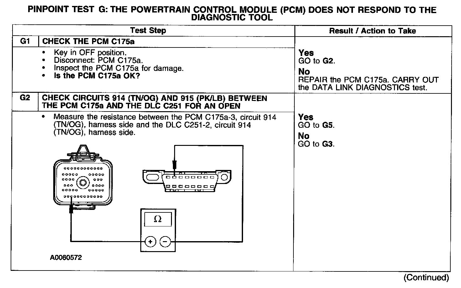
PINPOINT TEST G: THE POWERTRAIN CONTROL MODULE (PCM) DOES NOT RESPOND TO THE DIAGNOSTIC TOOLTest G1-G2:
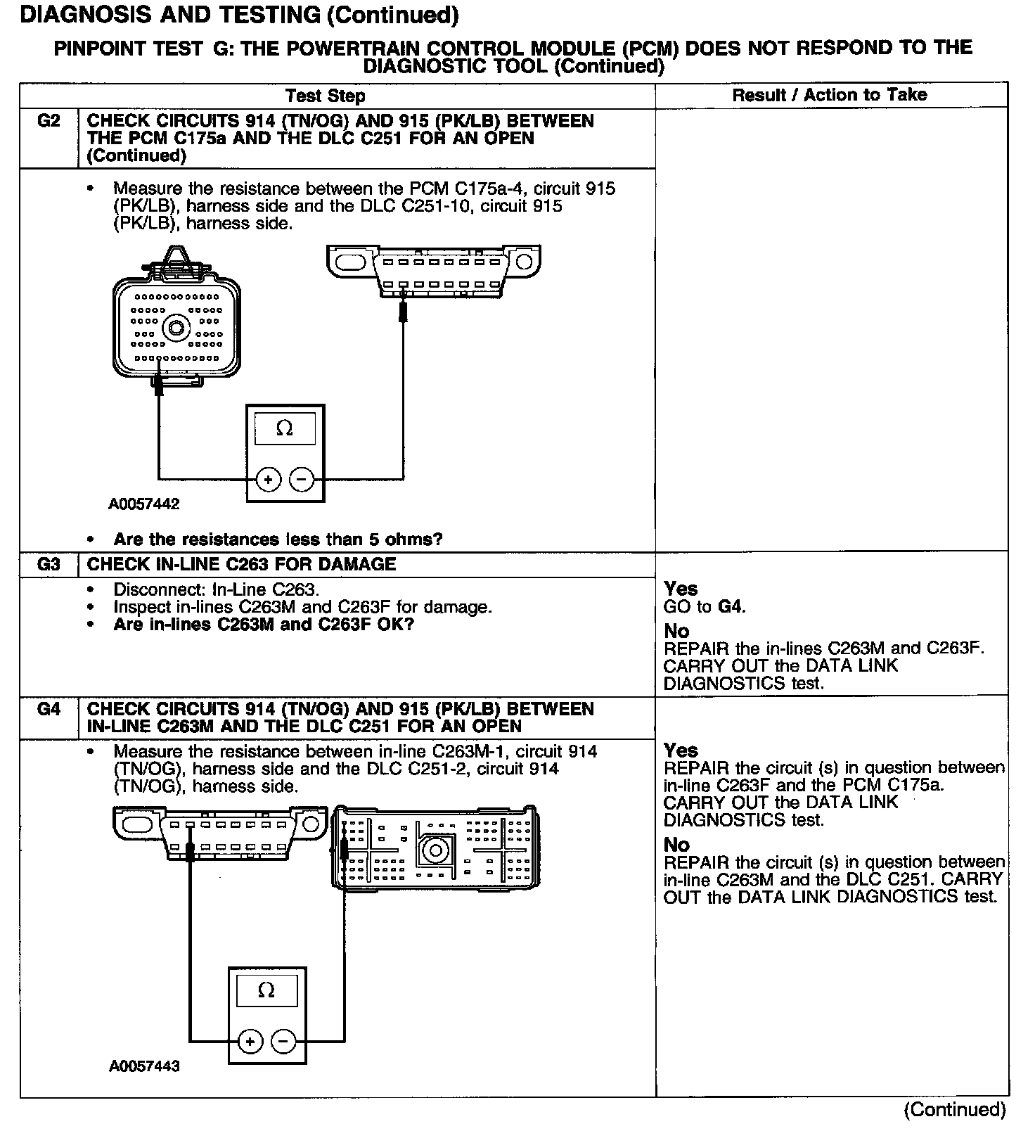
Test G2-G4:
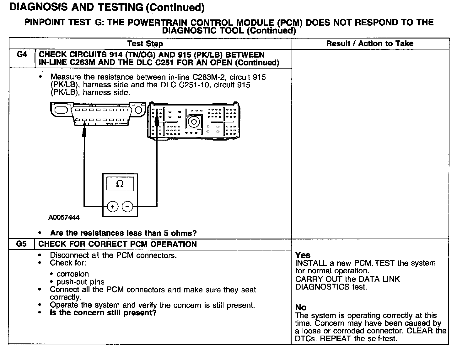
Test G4-G5:
Normal Operation
The PCM communicates with the diagnostic tool through the SCP communications network circuits 914 (TN/OG) and 915 (PK/LB). If one of the bus wires becomes shorted to ground or voltage, or if some but not all termination resistors are lost, communications can continue. Check circuits 914 (TN/OG) and 915 (PK/LB) between the PCM C175a and the data link connector (DLC) C251. Total resistance values must not be more than 5 ohms. If the resistance is more than 5 ohms there is an open in circuit 914 (TN/OG) or 915 (PK/LB), damage to the DLC C251, damage to the PCM C175a, or a problem in the in-line connector C263.
Possible Causes
- circuits 914 (TN/OG) or 915 (PK/LB) shorted to ground or open
- PCM C175a
- in-line C263
- DLC C251
- PCM