Steps 51 - 103
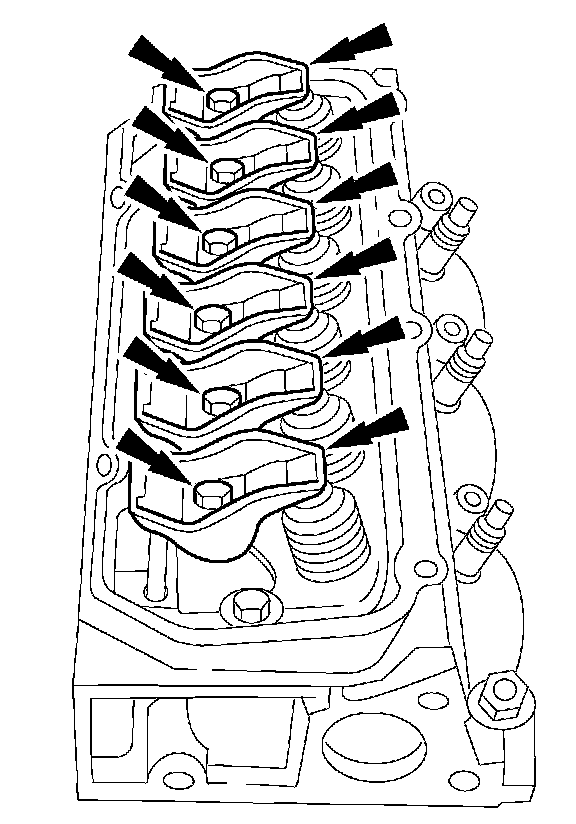
51. NOTE: If reusing the rocker arms, make sure to install them in their original location.
Install the rocker arms.
- Position the rocker arms and pivots.
- Hand-start the bolts.
- Tighten the bolts in two stages.
- Stage 1: Tighten to 5 Nm (44 inch lbs.).
- Stage 2: Tighten to 32 Nm (24 ft. lbs.).

52. NOTE: Inspect the valve cover gaskets for damage. Install a new gasket, if necessary.
Install the valve covers.
- Position the valve covers.
- Install the bolts.
- Install the stud bolts.
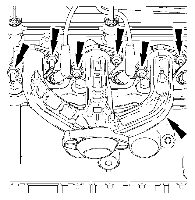
53. Using a new gasket, install the RH exhaust manifold. Loosely install the RH nuts.

54. Tighten the bolts in the sequence shown.
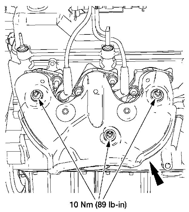
55. Install the heat shield and nuts.
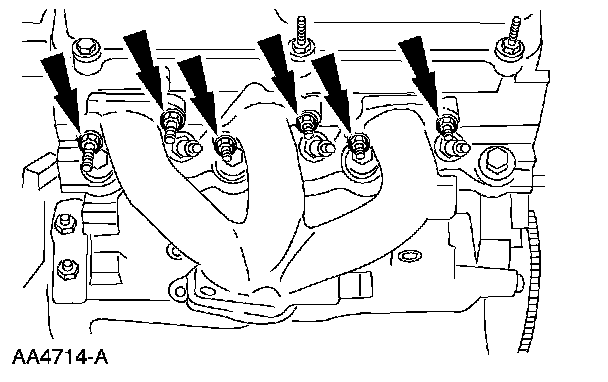
56. Using a new gasket, install the LH exhaust manifold. Loosely install the LH nuts.
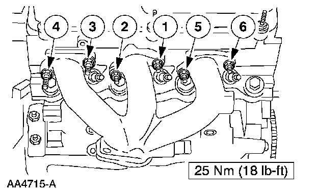
57. Tighten the bolts in the sequence shown.
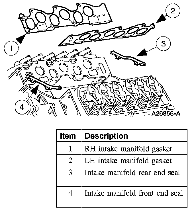
58. Refer to the illustration for intake manifold sealing components.
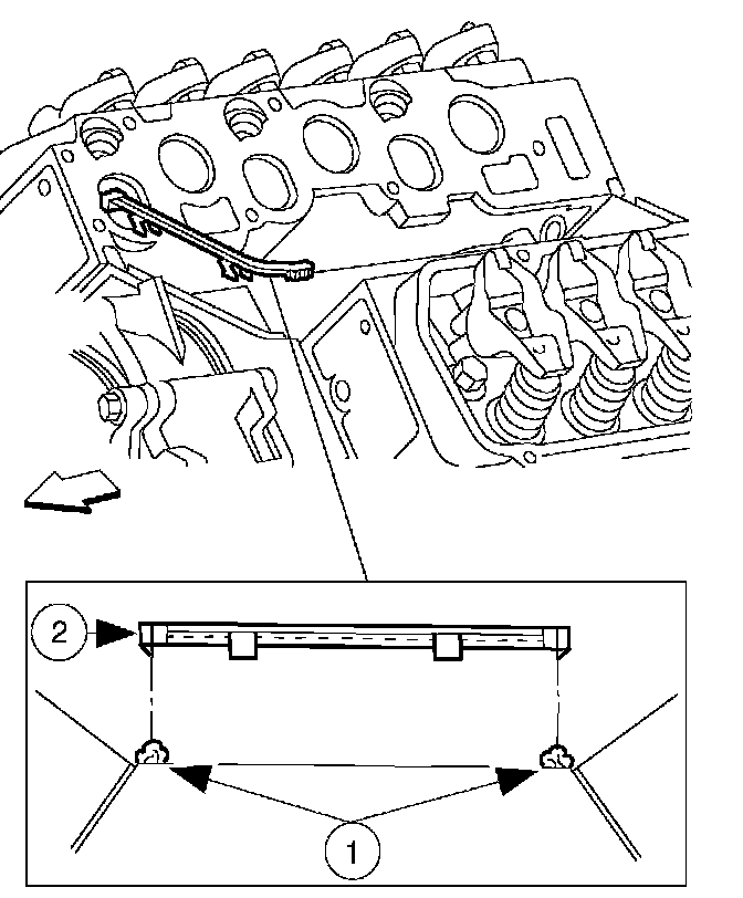
59. Install the lower intake manifold front and rear end seals.
1. Apply a bead of silicone gasket and sealant to the intake manifold front and rear end seal mounting points as indicated.
2. Install the lower intake manifold front and rear end seals.
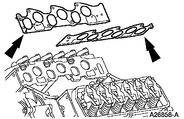
60. Position the intake manifold gaskets.
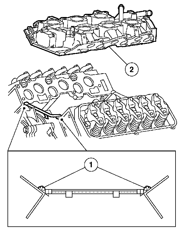
61. NOTE: The lower intake manifold must be installed within four minutes of applying the sealant.
Position the lower intake manifold.
1. Apply a bead of silicone gasket and sealant to the lower intake manifold mounting at the points indicated.
2. Position the lower intake manifold.
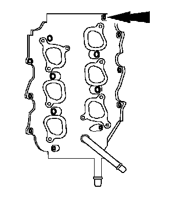
62. NOTE: Make sure the bolts are installed in the correct locations.
Install the six long bolts.
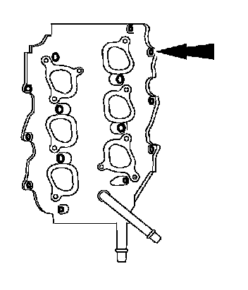
63. Install the eight short bolts.
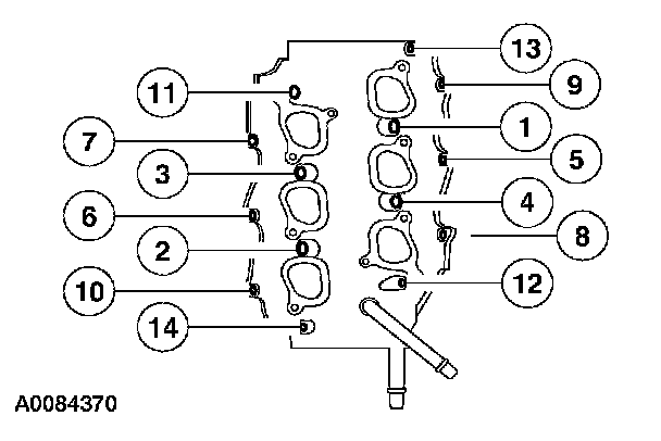
64. Tighten the lower intake manifold bolts in two stages in the sequence shown.
- Stage 1: Tighten to 5 Nm (44 inch lbs.).
- Stage 2: Tighten to 10 Nm (89 inch lbs.).
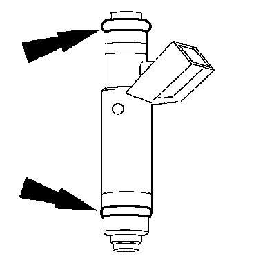
65. Install new O-rings on the fuel injectors.
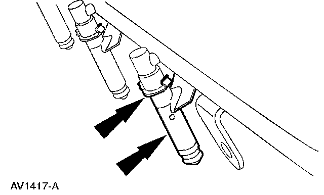
66. NOTE: Lubricate the O-ring seals with clean engine oil to aid installation.
Install the fuel injectors and retaining clips on the fuel supply manifold.
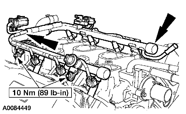
67. Install the fuel supply manifold, fuel injectors and fuel charging harness as an assembly.
- Install the bolts.
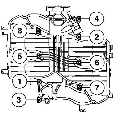
68. Using new gaskets, install the upper intake manifold and bolts.
- Tighten the upper intake manifold bolts in two stages in the sequence shown.
- Tighten the bolts to 6 Nm (53 inch lbs.).
- Tighten the bolts to 10 Nm (89 inch lbs.).
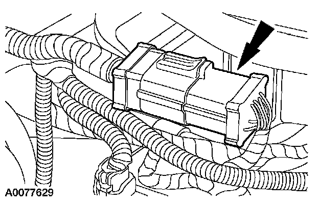
69. Position the engine harness onto the engine and connect the engine harness-to-fuel charging harness electrical connector.
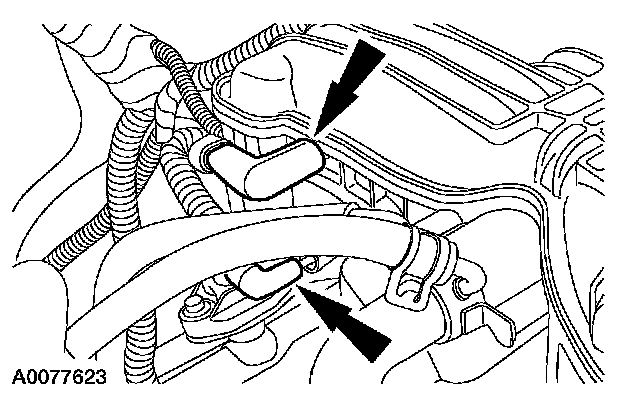
70. Position the vacuum harness onto the engine and connect the two vacuum harness connections.
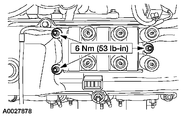
71. Install the ignition coil.
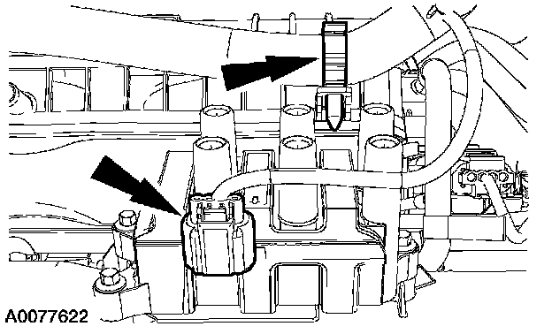
72. Install the engine harness pin-type retainer and connect the ignition coil electrical connector.
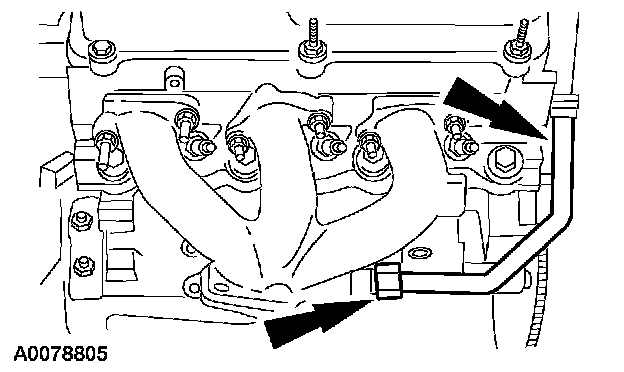
73. NOTE: Do not tighten the exhaust gas recirculation (EGR) system module-to manifold tube lower fitting.
Install the EGR system module-to-manifold tube.
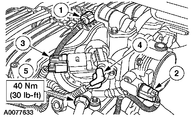
74. Connect the following.
1. Idle air control (IAC) electrical connector
2. Throttle position (TP) sensor electrical connector
3. Exhaust gas recirculation (EGR) system module electrical connector
4. EGR system module vacuum connector
5. EGR system module-to-exhaust manifold tube upper fitting
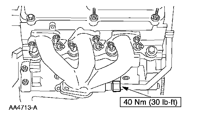
75. Tighten the exhaust gas recirculation (EGR) system module-to manifold tube lower fitting.
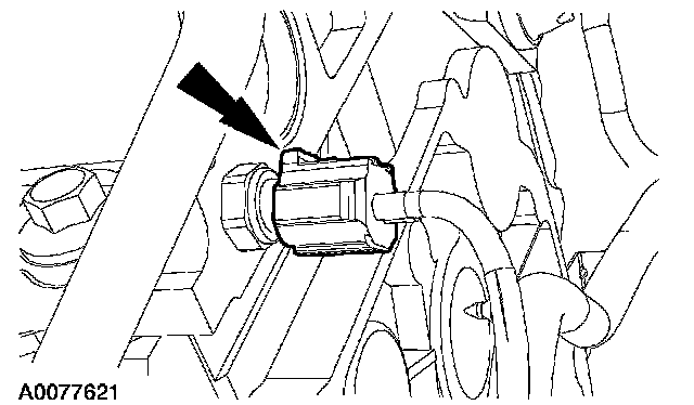
76. Connect the cylinder head temperature (CHT) sensor electrical connector.

77. Install the four engine harness pin-type retainers.
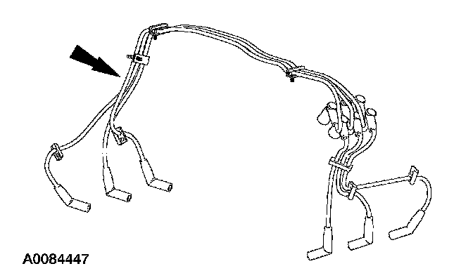
78. NOTE: Apply dielectric grease to the inside of the spark plug wire boots before attaching to the spark plugs and the ignition coil.
Install and connect the spark plug wires and retainers as an assembly.
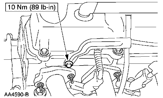
79. NOTE: Install a new oil level indicator tube O-ring seal.
Install the oil level indicator tube and the retaining nut.
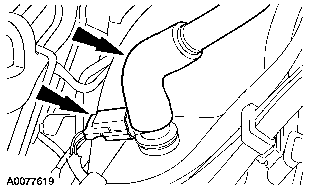
80. Connect the positive crankcase ventilation (PCV) valve electrical connector and install the PCV hose.
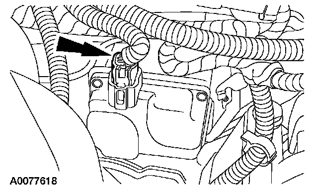
81. Connect the intake manifold runner control (IMRC) electrical connector.
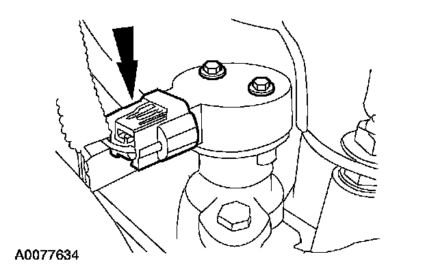
82. Connect the camshaft position (CMP) sensor electrical connector.

83. Connect the oil pressure sensor electrical connector and install the engine harness pin-type retainer.
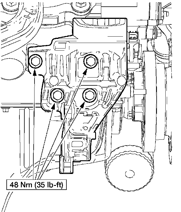
84. Install the RH engine mount bracket.
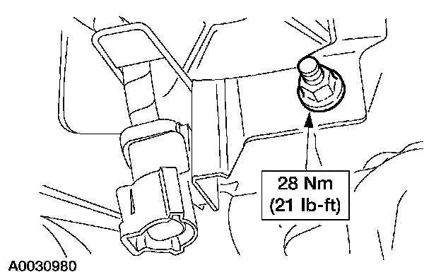
85. Install the catalyst monitor sensor electrical connector bracket.

86. Connect the crankshaft position (CKP) sensor electrical connectors.
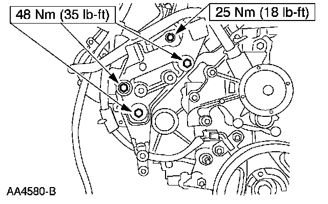
87. Install the power steering pump bracket and mounting bolts.

88. Install the accessory drive belt tensioner and bolts.
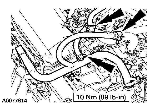
89. NOTE: Install a new coolant pump outlet tube O-ring and lubricate with clean engine coolant.
Install the coolant pump outlet tube.
- Install the two bolts.
- Connect the three coolant hoses.
- Reposition the clamps.
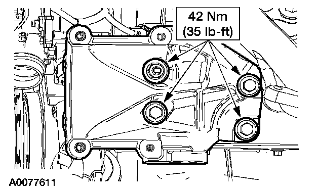
90. Install the A/C compressor bracket.
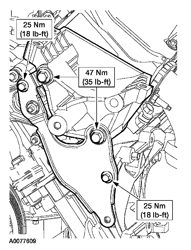
91. Install the A/C compressor mounting bracket brace and generator mounting bracket as an assembly.
- Install the bolts.
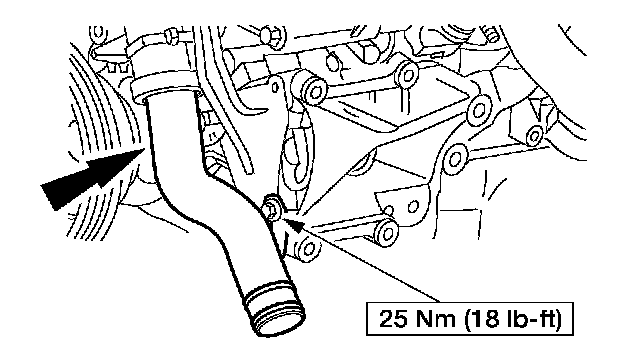
92. Install the coolant extension tube and bracket.
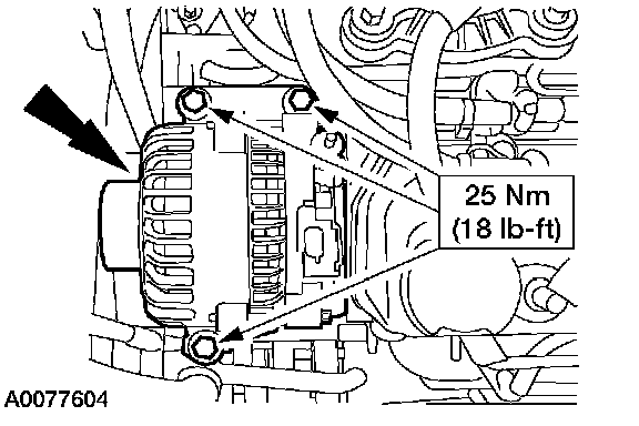
93. Install the generator and bolts.
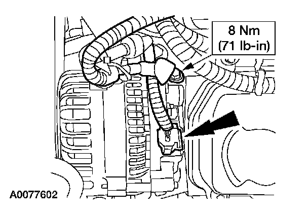
94. Connect the generator.
- Install the B+ wire terminal and nut.
- Connect the generator electrical connector.
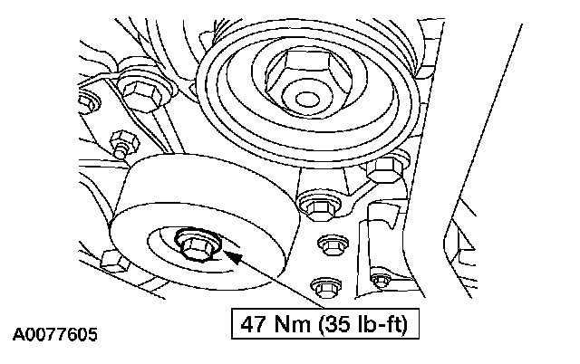
95. Install the accessory drive idler pulley.
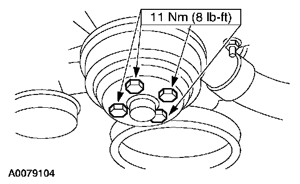
96. Install the coolant pump pulley and bolts.

97. Install the special tools.
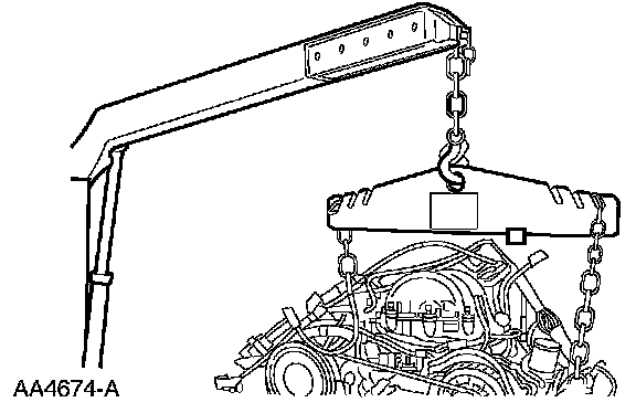
98. Install the engine lifting equipment.
99. Remove the engine from the stand.
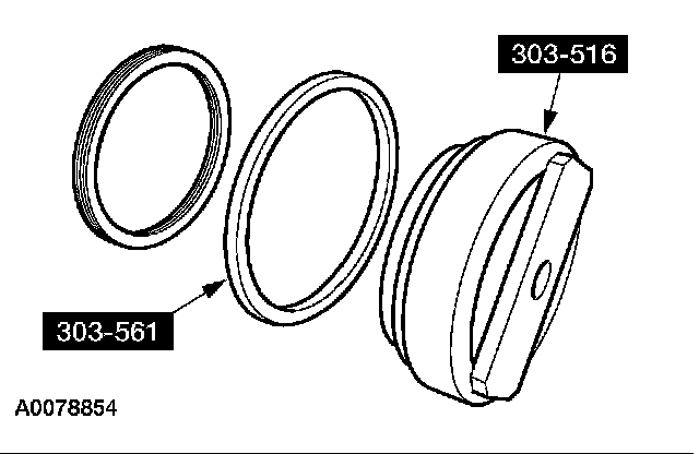
100. NOTE: Lubricate the crankshaft rear seal lips with clean engine oil prior to installation.
Assemble the special tools and the crankshaft rear seal.
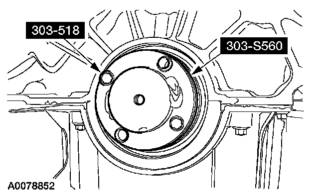
101. Install the special tools on the rear of the crankshaft.

102. Install the crankshaft rear seal. Tighten the center jack screw until the spacer contacts the engine block.
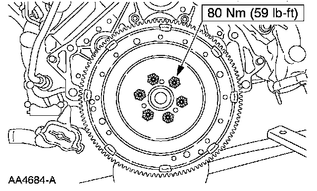
103. Install the flywheel and bolts.