Pinpoint Test I: The Keyless Entry Keypad Illumination Is Inoperative/Does Not Operate Correctly
Locks, Latches and Entry Systems

Pinpoint Tests
Pinpoint Test I: The Keyless Entry Keypad Illumination Is Inoperative/Does Not Operate Correctly
Refer to Wiring Diagram Set 117, Remote Keyless Entry and Alarm for schematic and connector information. Diagrams By Number
Normal Operation
When the SJB detects a keyless entry keypad button is pressed, the SJB provides voltage to the keyless entry keypad through circuit CPK28 (GN/BK). Ground for the keyless entry keypad is provided through circuit GD133 (BK).
This pinpoint test is intended to diagnose the following:
- Wiring, terminals or connectors
- Keyless entry keypad
- SJB
PINPOINT TEST I: THE KEYLESS ENTRY KEYPAD ILLUMINATION IS INOPERATIVE/DOES NOT OPERATE CORRECTLY
NOTICE: Use the correct probe adapter(s) when making measurements. Failure to use the correct probe adapter(s) may damage the connector.
NOTE: Failure to disconnect the battery when instructed will result in false resistance readings. Refer to Battery.
-------------------------------------------------
I1 CHECK THE SJB KEYPAD SWITCH PIDs
- Enter the following diagnostic mode on the scan tool: SJB DataLogger.
- Observe the SJB PID (KEY_PAD) while pressing each keyless entry keypad button.
- Do the PID values agree with the keypad button positions?
Yes
GO to I2.
No
Go To Pinpoint Test H. Pinpoint Test H: The Doors Do Not Lock/Unlock Using The Keyless Entry Keypad
-------------------------------------------------
I2 CHECK CIRCUIT GD133 (BK) FOR AN OPEN
- Ignition OFF.
- Disconnect: Negative Battery Cable.
- Disconnect: Keyless Entry Keypad C500.
- Measure the resistance between the keyless entry keypad C500-5, circuit GD133 (BK), harness side and ground.
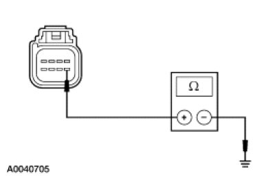
- Is the resistance less than 5 ohms?
Yes
GO to I3.
No
REPAIR the circuit. TEST the system for normal operation.
-------------------------------------------------
I3 CHECK FOR CONSTANT VOLTAGE
- Connect: Negative Battery Cable.
- Ignition ON.
- Measure the voltage between the keyless entry keypad C500-2, circuit CPK28 (GN/BK), harness side and ground.
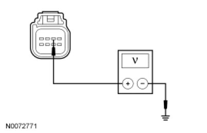
- Is any voltage present?
Yes
GO to I4.
No
GO to I5.
-------------------------------------------------
I4 CHECK CIRCUIT CPK28 (GN/BK) FOR A SHORT TO VOLTAGE
- Ignition OFF.
- Disconnect: SJB C2280a.
- Ignition ON.
- Measure the voltage between the keyless entry keypad C500-2, circuit CPK28 (GN/BK), harness side and ground.
- Is any voltage present?
Yes
REPAIR the circuit. TEST the system for normal operation.
No
GO to I7.
-------------------------------------------------
I5 CHECK FOR SJB OUTPUT
- Ignition OFF.
- Measure the voltage between the keyless entry keypad C500-2, circuit CPK28 (GN/BK), harness side and ground while connecting a fused (5A) jumper wire between the keyless entry keypad C500-1, circuit CPK29 (GY/BU), harness side and ground.
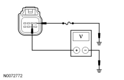
- Is the voltage greater than 10 volts?
Yes
INSTALL a new keyless entry keypad. REFER to Keyless Entry Keypad Service and Repair. TEST the system for normal operation.
No
GO to I6.
-------------------------------------------------
I6 CHECK CIRCUIT CPK28 (GN) FOR AN OPEN OR A SHORT TO GROUND
- Disconnect: SJB C2280a.
- Measure the resistance between the SJB C2280a-18, circuit CPK28 (WH/GN), harness side and the keyless entry keypad C500-2, circuit CPK28 (GN/BK), harness side; and between the SJB C2280a-18, circuit CPK28 (WH/GN), harness side and ground.
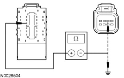
- Is the resistance less than 5 ohms between the SJB and the keyless entry keypad; and greater than 10,000 between the SJB and ground?
Yes
GO to I7.
No
REPAIR the circuit. TEST the system for normal operation.
-------------------------------------------------
I7 CHECK FOR CORRECT SJB OPERATION
- Disconnect all the SJB connectors.
- Check for:
- corrosion
- damaged pins
- pushed-out pins
- Connect all the SJB connectors and make sure they seat correctly.
- Operate the system and verify the concern is still present.
- Is the concern still present?
Yes
INSTALL a new SJB. TEST the system for normal operation.
No
The system is operating correctly at this time. The concern may have been caused by a loose or corroded connector.
-------------------------------------------------