Component Tests and General Diagnostics
THROTTLE OPENER SYSTEM
1. Check the system vacuum hoses for proper routing according to the underhood label as well as leaks and deterioration.
2. Start the engine with the air conditioning off, transmission in neutral, and brakes set.
3. Allow the engine to reach operating temperature then remove the vacuum hose at the throttle opener. There should be no vacuum at the hose indicating the system is functioning properly.
a. If vacuum is available at the hose, use a test light to verify that voltage is not present at the solenoid valve wire connections.
b. If there is voltage present at the solenoid valve wire connections, verify that there is no continuity across the air conditioning switch when the switch is in the "Off" position.
c. If there is continuity when the switch is in the off position replace the switch and repeat steps 2 and 3.
d. If there is no voltage at the solenoid valve wire connections replace the solenoid valve and repeat steps 2 and 3.
Fig. 56 Testing the throttle opener for A/C:
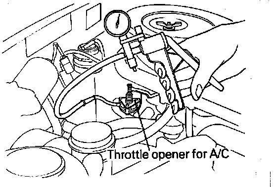
4. Attach a hand vacuum pump to the throttle opener, Fig. 56 and apply vacuum. Vacuum should hold.
a. If vacuum holds the throttle opener is functioning properly.
b. If vacuum does not hold replace the throttle opener.
5. Push the air conditioning switch in and turn the blower fan switch to "High". There should be vacuum at the throttle opener vacuum hose indicating proper system operation.
a. If there is vacuum at the throttle opener vacuum hose reconnect the vacuum hose to the throttle opener.
b. If there is no vacuum at the throttle opener vacuum hose remove the manifold vacuum hose from the solenoid valve and verify that vacuum is present.
c. If vacuum is not available at the hose clean the intake manifold vacuum connection and repeat step 5.
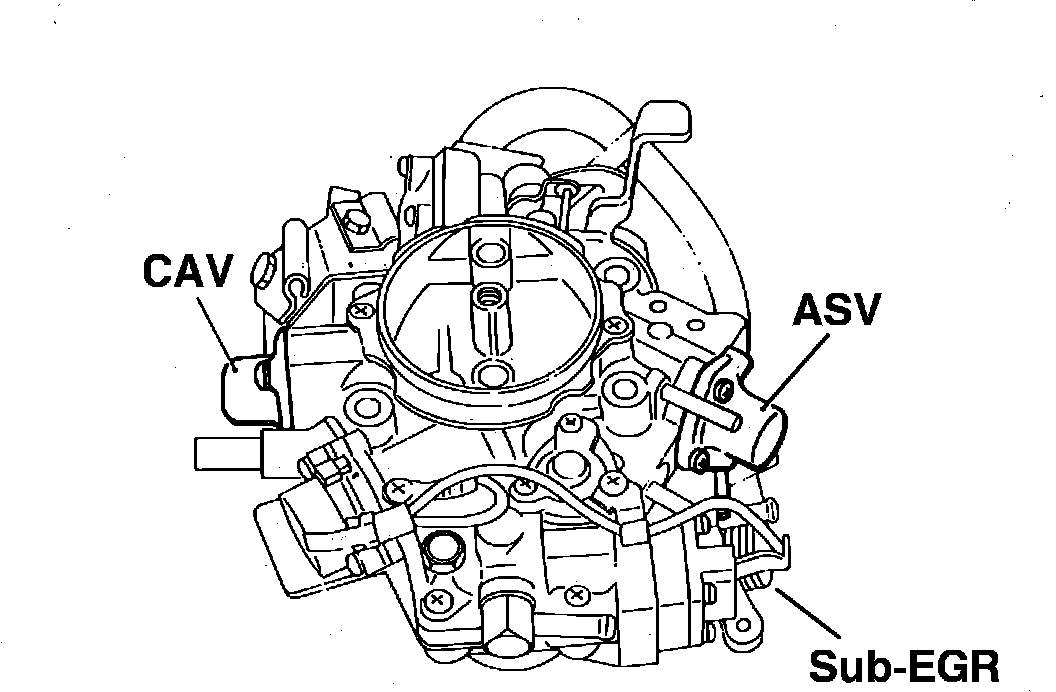
Fig. 12 Component locations:
AIR SWITCHING VALVE
1. Run the engine at idle.
2. Disconnect the solenoid valve connector to turn off the solenoid valve. (Manifold vacuum will act on the air switching valve, causing the valve to open.) If the idle speed falls excessively or the engine stalls, the air switching valve and solenoid valve are operating properly. If the speed does not change, check the vacuum passage for clogging and check the condition of air switching valve or solenoid valve.
3. With the engine at idle, battery voltage should be present at the solenoid valve connector. If no voltage is present, the electrical wiring or engine speed sensor is defective.
4. Increase the engine speed to 1,500 rpm. Verify that voltage is present at the solenoid valve connector. If there is no voltge, the engine speed sensor is defective.
5. Increase the engine speed to 2,500 rpm. Verify that no voltage is present at the solenoid valve connector. If there is voltage, the engine speed sensor is defective.