Choke Shim Installation Check
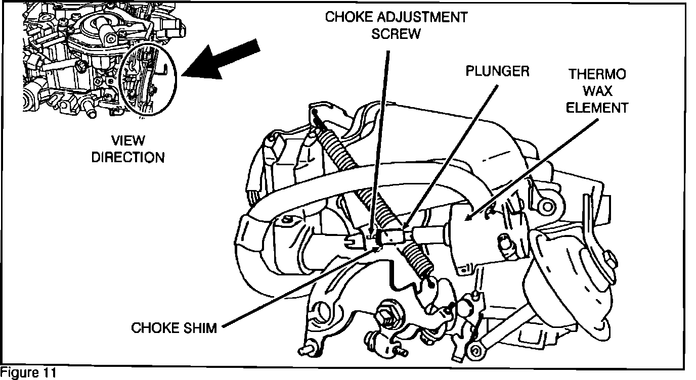
1. Check the installation of the choke shim. As shown in Figure 11, the shim should be firmly seated between the thermo wax element's plunger and the choke adjustment screw. If the choke shim is properly installed, continue with the Jet Mixture Solenoid Valve installation procedure.
2. If the choke shim is missing or installed incorrectly, a new shim must be installed. The shim is contained in the EMR-90-002 emission kit (MD164089).
BEFORE INSTALLING THE CHOKE SHIM READ THROUGH THE FOLLOWING 1 TO 6 STEPS.
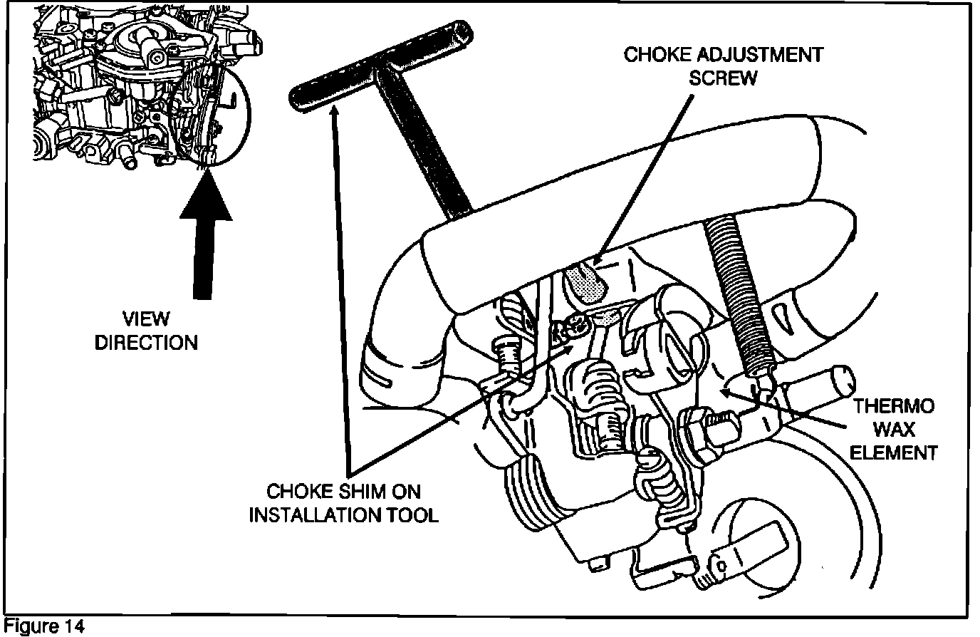
1. Install the choke shim that is included in the emission kit as described in Figures 12, 13, 14, 15, 16, and 17.
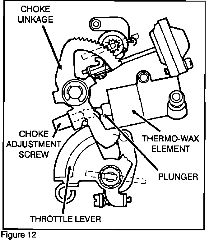
Shown in Figure 12 is a basic outline view of the choke mechanism.
Note:
The area between the choke adjustment screw and the plunger is behind the choke linkage and is hidden from view.
Note:
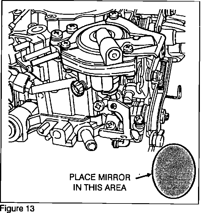
A mirror must be placed beside the carburetor next to the throttle lever. This will allow you to see the area that the choke shim must be installed in.
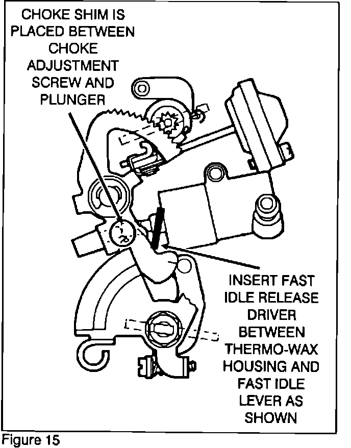
2. Using the fast idle release driver special tool, insert the tool between the thermo wax element housing and the choke linkage (Figure 15).
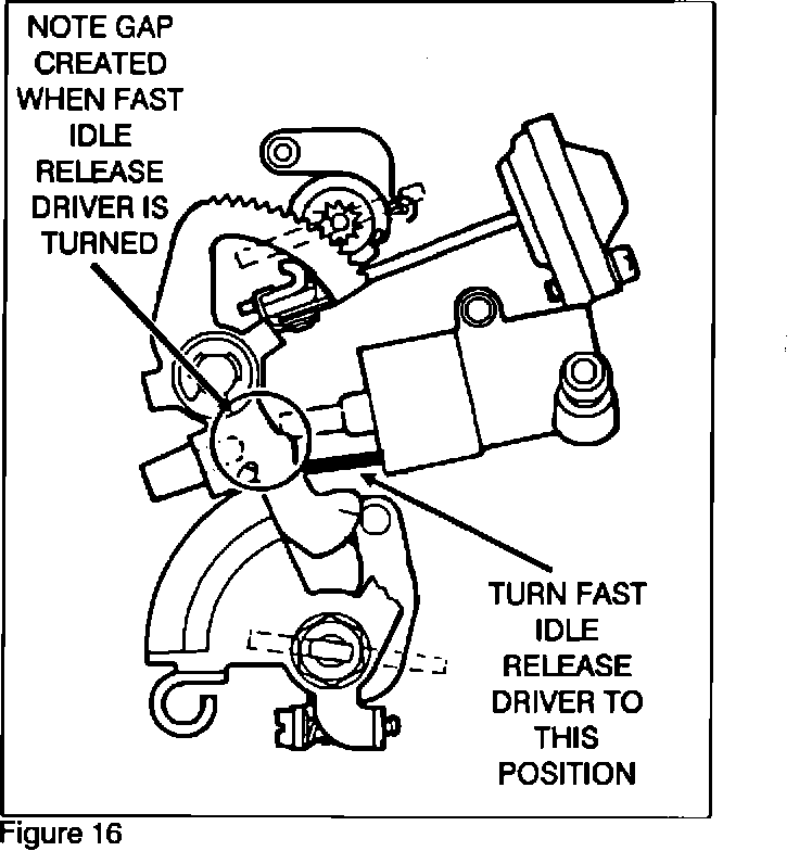
3. Spread the choke linkages to create a gap between the choke adjustment screw and the plunger of the thermo wax element (Figure 16). Make sure not to interfere with the throttle lever or other linkages.
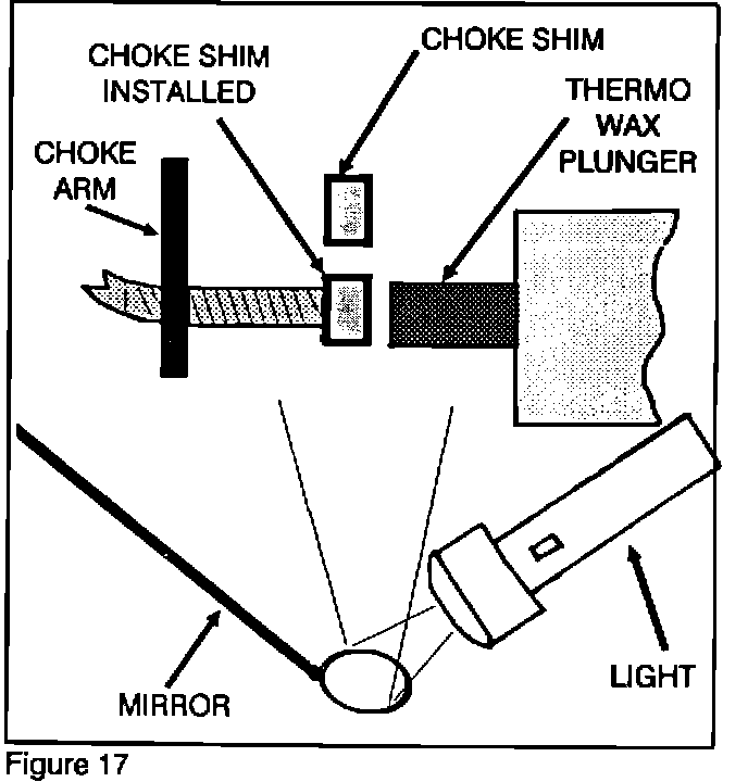
4. With the linkages spread, install the cap portion of the Choke Shim onto the threaded end of the choke adjustment screw. The cap portion of the shim should be inserted between the plunger and the choke adjustment screw (Figure 17).
5. Remove the fast idle release driver. Carefully twist the handle of the Choke Shim and allow the handle to break off from the cap portion.
6. Using a flashlight and a mirror, visually inspect the final installation of the Choke Shim. It must be securely on the end of the adjustment screw.