Carburetor Removal
1. Slowly and carefully remove the radiator pressure cap.
WARNING:
Be aware of high coolant temperature and pressure. Do not allow the hot coolant to splash. Hot coolant will cause burns.
2. Drain the cooling system.
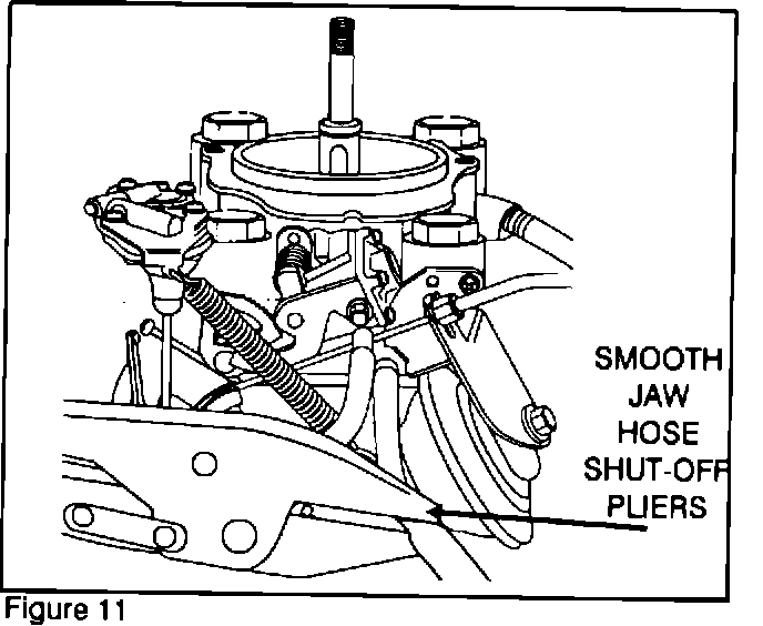
3. To prevent excessive coolant leakage, use smooth jaw hose shut-off pliers to pinch off the coolant hose from the intake manifold to the choke thermo wax housing (Figure 11). Then twist and disconnect the hose from the carburetor.
CAUTION:
Avoid using standard locking clamp pliers (Vise-Grips) with serrated jaws as they may damage hoses.
4. Disconnect the accelerator cable and wire harness connector from the carburetor. Disconnect the fuel lines and hose connections.
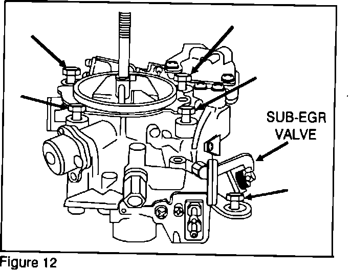
5. Remove the nut and lock washer at the left rear corner of the carburetor near the Sub-EGR Valve and the four carburetor through bolts and washers (Figure 12).
Lift the carburetor off the intake manifold.
Note:
Usually a quick, hard pull will separate the carburetor from the intake manifold. Cover the exposed intake manifold ports with a shop towel.
6. Support the carburetor in a vise using MIT209769 carburetor aligning pins.
CAUTION:
Do not damage the throttle linkage that extends below the base of the carburetor.
BEFORE INSTALLING THE CHOKE
SHIM READ THROUGH THE
FOLLOWING STEPS 1 THRU 6.
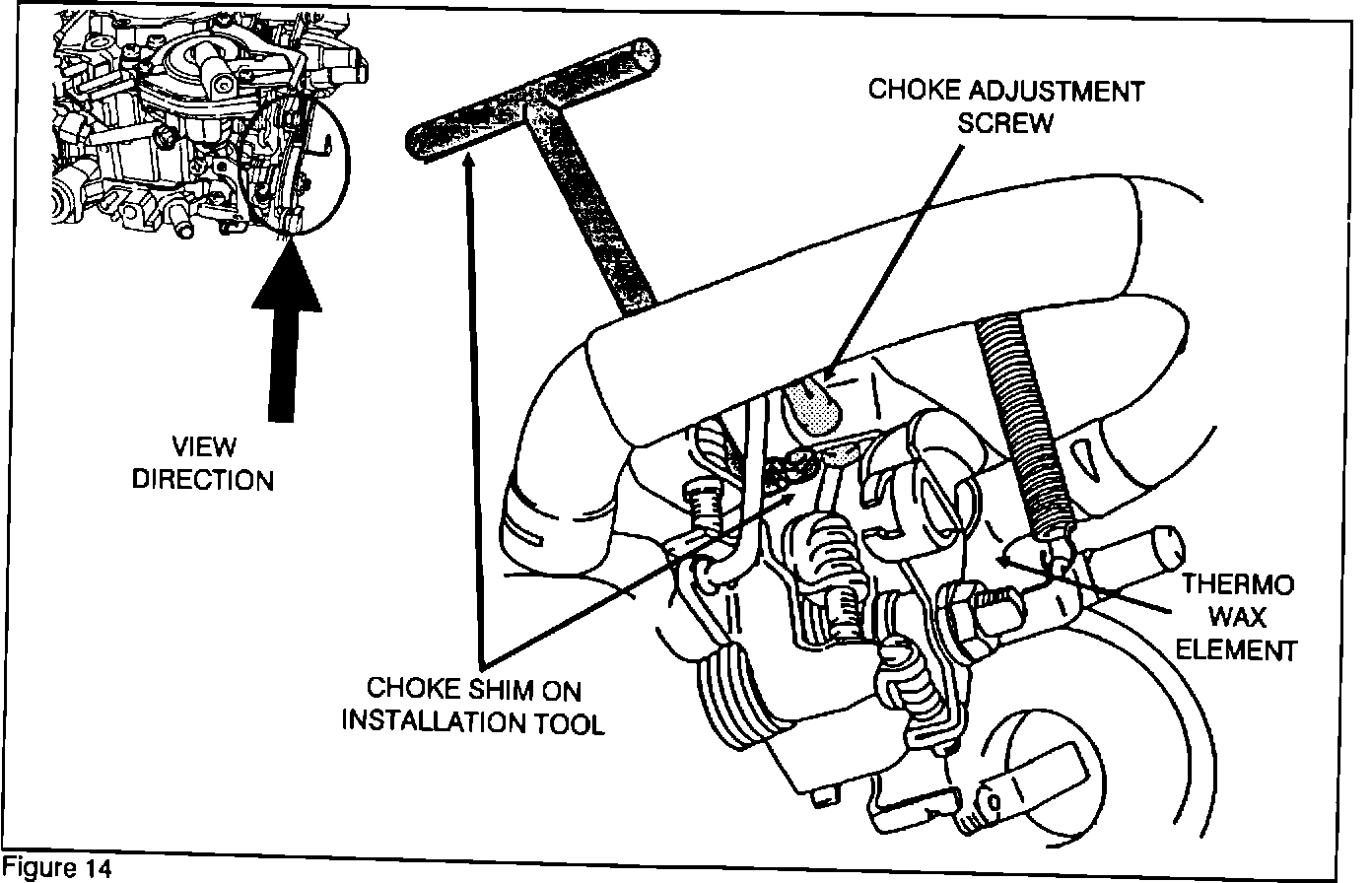
1. Install the choke shim that is included in the emission kit as described in Figures 13, 14, 15, 16, and 17.
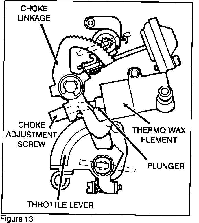
Shown in Figure 13 is a basic outline view of the choke mechanism.
Note:
The area between the choke adjustment screw and the plunger is behind the choke linkage and is hidden from view.
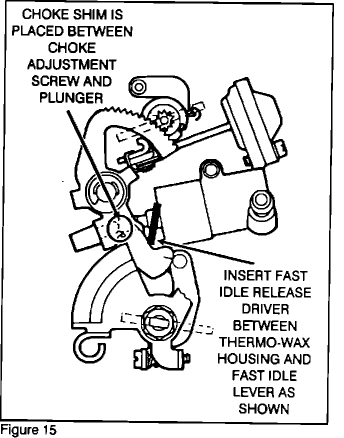
2. Using the fast idle release driver special tool, insert the tool between the thermo wax element housing and the choke linkage (Figure 15).
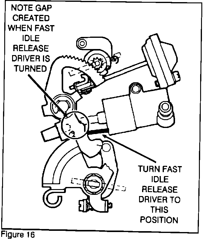
3. Spread the choke linkages to create a gap between the choke adjustment screw and the plunger of the thermo wax element (Figure 16). Make sure not to interfere with the throttle lever or other linkages.
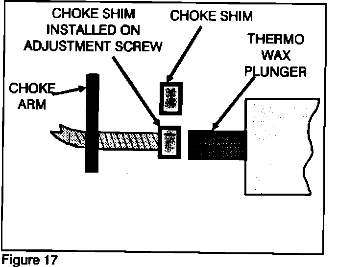
4. With the linkages spread, install the cap portion of the choke shim onto the threaded end of the choke adjustment screw. The cap portion of the shim should be inserted between the plunger and the choke adjustment screw (Figure 17).
5. Remove the fast idle release driver.
Carefully twist the handle of the choke shim and allow the handle to break off from the cap portion.
6. Visually inspect the final installation of the Choke Shim. It must be securely on the end of the adjustment screw.