Evaporative Emissions System: Testing and Inspection
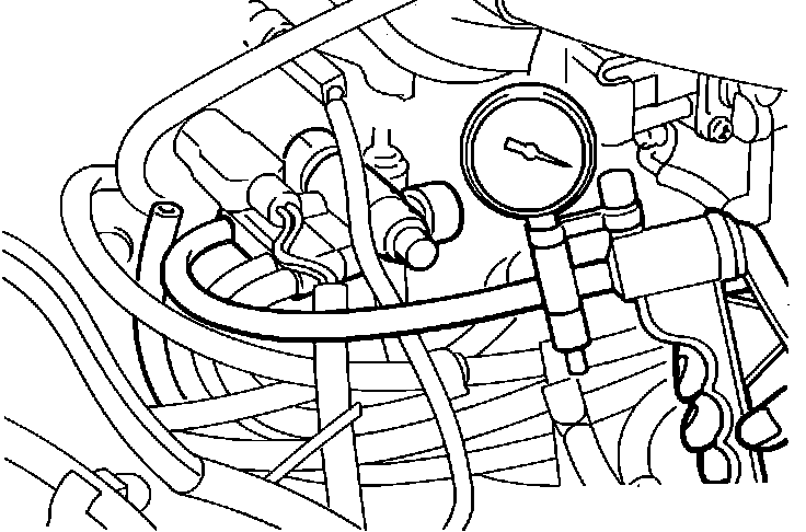
Fig. 135 Testing purge control system:
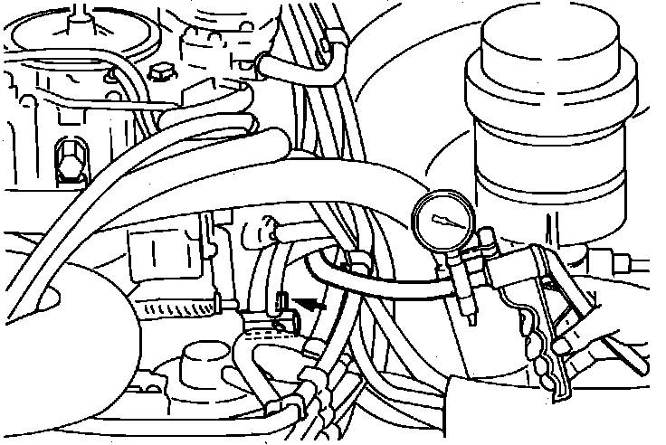
SYSTEM TESTING
1. Disconnect the black vacuum hose from the intake manifold nipple and plug the nipple.
2. Connect a hand vacuum pump to the disconnected black vacuum hose, Fig. 135.
3. Verify that when the engine is cold (coolant temperature less than 50 degrees C or 122 degrees F) that it is possible to achieve a steady 53 kpa (15 in. Hg) of vacuum when the engine is held at 2,500 rpm.
4. Allow the engine to warm up (coolant temperature greater than 85 degrees C or 185 degrees F) and verify that it is possible to achieve a steady 53 kPa (15 in. Hg) of vacuum while the engine idles.
5. Accelerate the engine to 2,500 rpm and verify that vacuum leaks.
Fig. 133 Testing bowl vent valve:
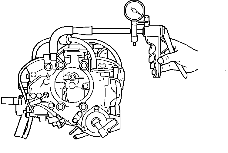
BOWL VENT VALVE
CAUTION!
Check the bowl vent valve after the engine has been allowed to cool. If the engine is hot fuel can gush out of the BVV nipple.
1. Remove the air cleaner.
2. Disconnect the bowl vapor hose from the bowl vent valve (BVV) nipple and connect a hand vacuum pump to the BVV nipple, Fig. 133.
3. Apply a vacuum of 20 kPa (6.0 in. Hg) to the BVV and verify that when the engine is running at idle the BVV holds vacuum and leaks when the engine is stopped.
Overfill Limiter (Two Way Valve):

OVERFILL LIMITER VALVE
Remove the overfill limiter valve and blow gently through both ends. Air should pass through the valve in both directions with slight resistance.
Fig. 136 Testing purge control valve:
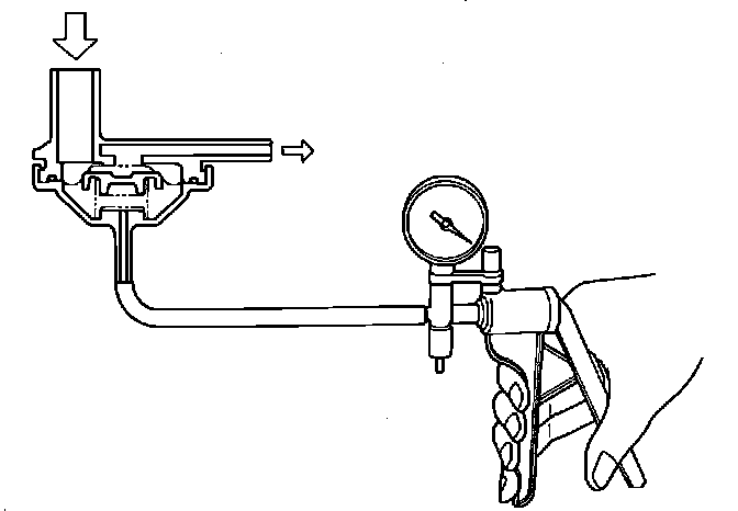
PURGE CONTROL VALVE
1. Remove the purge control valve.
2. Connect a hand vacuum pump to the nipple of the PCV, Fig. 136.
3. Apply a vacuum of 53 kPa (15 in. Hg) and verify that the diaphragm chamber is leak tight.
4. Remove the vacuum and verify that air will not pass through the purge control valve.
5. Apply 27 kPa (8 in. Hg) of vacuum and verify that air will pass through the purge control valve.
Fig. 137 Testing thermo valve:
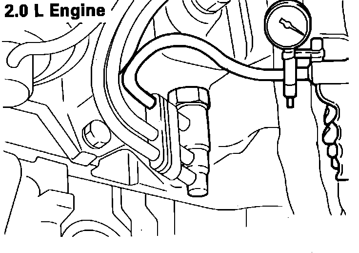
THERMO VALVE
1. Disconnect the vacuum hose (white stripe) from the thermo valve and connect a hand vacuum pump to the thermo valve, Fig. 137.
2. Apply vacuum and verify that when the engine is cold (coolant temperature less than 10 degrees C or 50 degrees F) that vacuum leaks through the thermo valve.
3. Warm up the engine (coolant temperature greater than 25 degrees C or 77 degrees F) and verify that vacuum does not leak.
Fig. 138 Testing thermo valve:
THERMO VALVE
4. Disconnect the vacuum hose (white stripe) from the thermo valve and connect a hand vacuum pump to the thermo valve, Fig. 138.
5. Apply vacuum and verify that when the engine is cold (coolant temperature less than 10 degrees C or 50 degrees F) that vacuum leaks through the thermo valve.
6. Warm up the engine (coolant temperature greater than 25 degrees C or 77 degrees F) and verify that vacuum does not leak.
Fig. 139 Testing thermo valve:
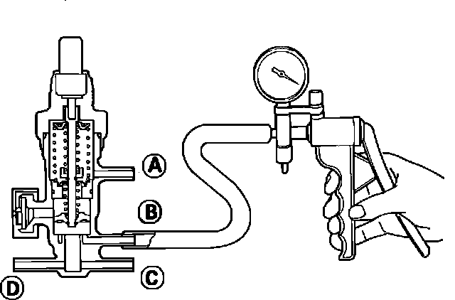
THERMO VALVE
7. Disconnect all vacuum hoses from the thermo valve.
8. Connect a hand vacuum pump one at a time to nipples (B), (C), and (D), plug the unused nipples, and perform the following steps for each port;
a. Verify that when the engine is cold (coolant temperature less than 40 degrees C or 104 degrees F) vacuum leaks.
b. Allow the engine to warm up (coolant temperature greater than 80 degrees C or 176 degrees F) that vacuum leaks.
Note: The thermo valve also controls the choke breaker, EGR, and choke opener. If the thermo valve fails and must be replaced use 3M locking sealant 4171 or equivalent and torque the thermo valve to 20 to 40 Nm (15-30 ft. lbs.). Do not use wrenches or pliers on the resin part of the valve during installation.