Main Relay (Computer/Fuel System): Testing and Inspection
Fig. 50 Control relay terminal identification.:
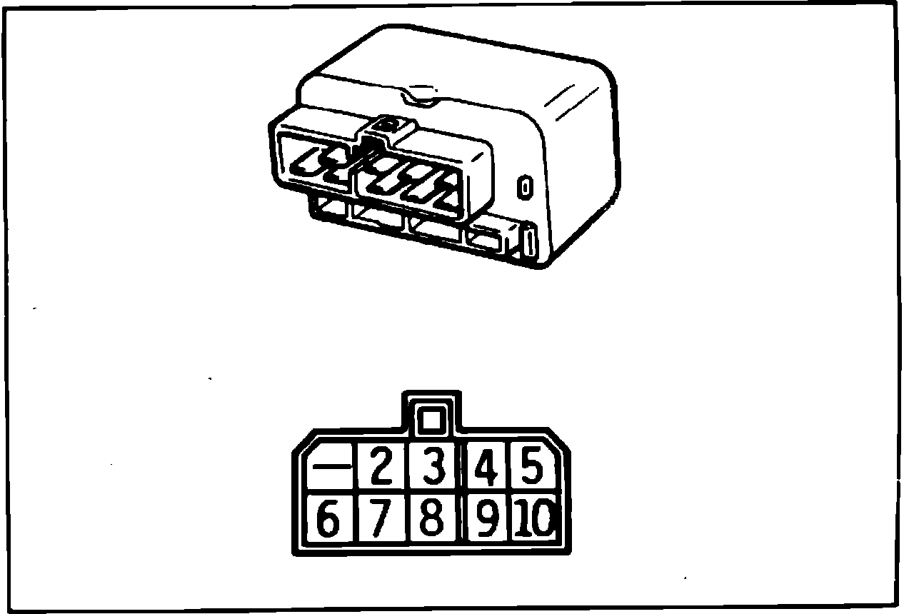
1. Remove glove compartment, then remove control relay.
2. Connect jumper wires from 12 volt battery positive terminal to relay terminal 10 and battery negative terminal to relay terminal 8, Fig. 50.
3. Measure voltage at relay terminals 4 and 5. With jumper wire connected between battery negative terminal and relay terminal 8, 12 volts should be indicated at relay terminals 4 and 5. With jumper wire disconnected, 0 volts should be indicated at terminals 4 and 5.
4. Connect jumper wires between battery negative terminal and relay terminal 6 and battery positive terminal and relay terminal 9.
5. Check for continuity between terminals 2 and 3. With jumper wire connected between battery positive terminal and relay terminal 9, continuity should exist between relay terminals 2 and 3. When jumper wire is disconnected from from terminal 9, continuity should not exist.
6. Connect jumper wires between battery positive terminal and relay terminal 3 and battery negative terminal and relay terminal 7.
8. Measure voltage at relay terminal 2 with jumper connected and disconnected from terminal 7. With jumper wire connected to relay terminal 7, 12 volts should be present at relay terminal 2. With jumper disconnect, 0 volts should be indicated at relay terminal 2.
9. If relay does not function as described above, replace relay.