Federal
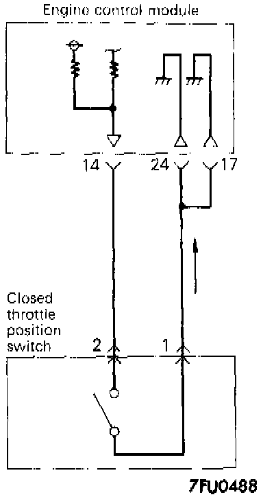
CIRCUIT DIAGRAM
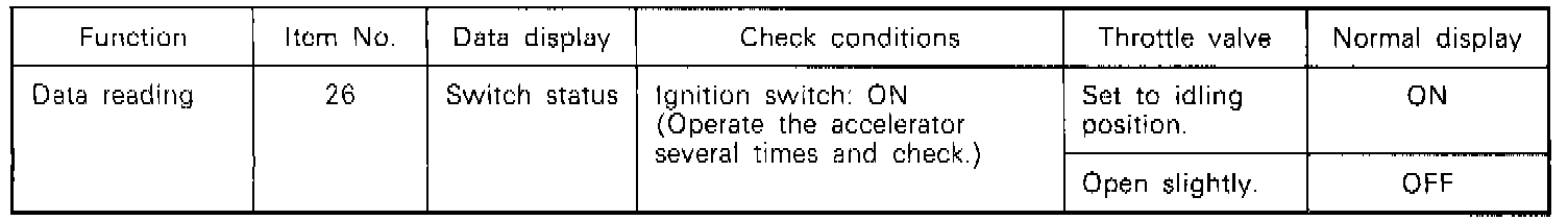
INSPECTION USING SCAN TOOL
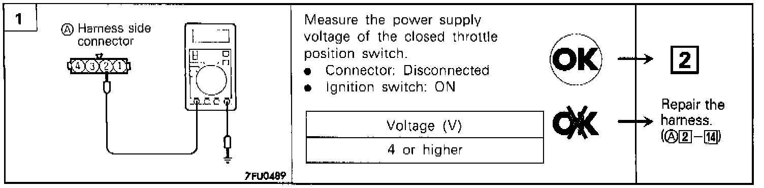
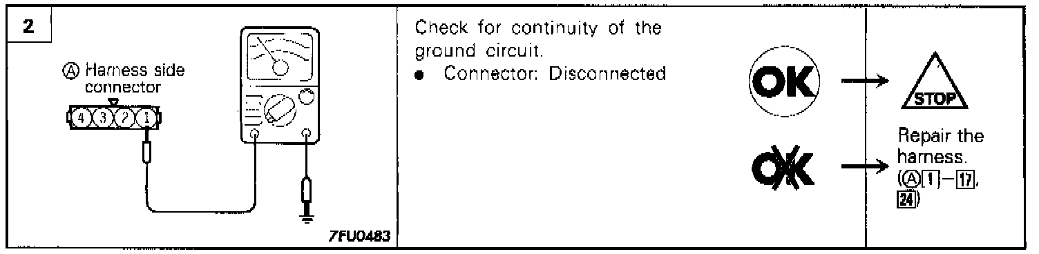
HARNESS INSPECTION PROCEDURE
COMPONENT TEST PROCEDURE
1. With the accelerator pedal released, check to be sure that the throttle valve lever or the fixed speed adjusting screw is closed.
NOTE: If it is not closed, adjust the fixed speed adjusting screw.
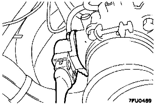
2. Disconnect the throttle position sensor connector.
3. Check the continuity across the throttle position sensor connector terminal 1 (Sensor ground) and 2 (Closed throttle position switch)
Released: Conductive (0 Ohms)
Depressed: Non-conductive (infinite Ohms)
NOTE: If there is no continuity when the accelerator pedal is returned, loosen the throttle-position sensor installation screw; then, after turning all the way in the clockwise direction, check again.
4. The closed throttle position switch is part of the throttle position sensor. Replace the throttle-position sensor if there is a malfunction.
NOTE: Adjust the throttle position sensor after replacement.
TROUBLESHOOTING HINTS
- If there is an abnormal condition of the closed throttle position switch output even though the results of the checking of the closed throttle position switch harness and of the component itself indicate a normal condition, the cause may be presumed to be one of the following.
- Improper adjustment of the accelerator cable or the cruise-control cable.
- Improper adjustment of the fixed speed adjusting screw.