Oscilloscope Patterns and Waveforms
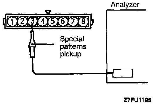
Wave Pattern Inspection Using an Analyzer Measurement Method
1. Disconnect the volume air flow sensor connector, and connect the special tool (test harness: MB991348) in between. (All terminals should be connected.)
2. Connect the analyzer special patterns pickup to terminal (3) of the volume air flow sensor connector.
Note: Alternative method of connection (when test harness is not available): connect the analyzer special patterns pickup to ECM terminal (70).
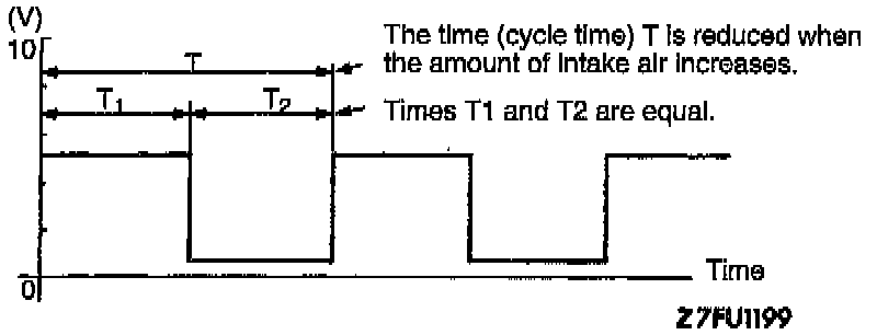
Standard wave pattern
Wave pattern observation points: check that cycle time T becomes shorter and the frequency increases when the engine speed is increased.
Observation conditions: Engine idling at 700 rpm (Pattern changes with engine speed changes)
EXAMPLES OF ABNORMAL WAVE PATTERNS
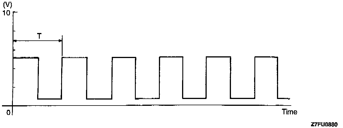
Example 1
- Cause of problem: malfunction of sensor interface
- Wave pattern characteristics: rectangular wave pattern is output even when the engine is not started.
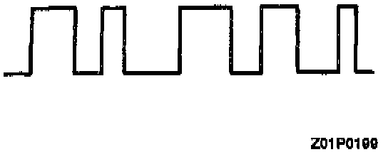
Example 2
- Cause of problem: damaged rectifier or vortex generation column
- Wave pattern characteristics: Unstable wave pattern with non-uniform frequency. However, when an ignition leak occurs during acceleration, the wave pattern will be distorted temporarily, even if the volume air flow sensor is normal.