Cranking Signal: Testing and Inspection
INSPECTION
Using Scan Tool
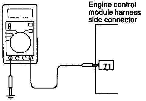
HARNESS INSPECTION
STEP 1. Measure the engine control module input voltage.
- Engine control module connector: Disconnected
- Ignition switch: START
Voltage (V): 8 or higher
OK: GO TO STEP 2
NG: Repair the harness. (71 - Ignition switch)
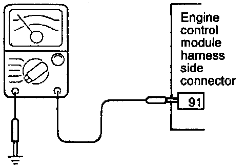
STEP 2. Check for continuity in the ground circuit.
- Engine control module connector: Disconnected
OK: STOP
NG: Repair the harness. (91 - Ground)