Charging A/C System
For the vehicles without the sight glass, use the refrigerant recovery station to charge the refrigerant. From July 1997 For the vehicles with the sight glass, charge the refrigerant by the following procedures. Up to June 1997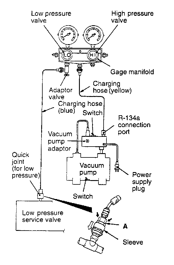
1. With the handles turned in all the way (valves closed), install the adaptor valve to the low-pressure side of the age manifold.
2. Connect the charging hose (blue) to the adaptor valve.
3. Connect the quick joint (for low pressure) to the charging nose (blue).
4. Connect the quick joint (for low pressure) to the low pressure service valve.
NOTE: The low-pressure service valve should be connected to the compressor.
CAUTION:
1. Use tools that are designed for R-134a.
2. To connect the quick joint, press section A firmly against the service valve until a click is heard. When connecting, run your hand along the hose while pressing to ensure that there are no bends in the hose.
5. lose the high and low pressure valves of the gage manifold.
6. Install the vacuum pump adaptor to the vacuum pump.
7. Connect the vacuum pump plug to the vacuum pump adaptor.
8. Connect the charging hose (yellow) to the R-134a connection port of the vacuum pump adaptor.
9. Tighten the adaptor valve handle (valve open).
10. Open the low pressure valve of the gage manifold.
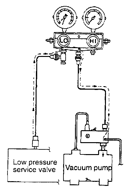
11. Turn the power switch of the vacuum pump to the ON position.
NOTE: Even if the vacuum pump power switch is turned ON, the vacuum pump will not operate because of the power supply connection in step (7).
12. Turn the vacuum pump adaptor switch to the R-134a side to start the vacuum pump.
CAUTION: Do not operate the air conditioning compressor to carry out evacuation.
13. Evacuate to a vacuum reading of 100 kPa (29.5 in.Hg) or higher (takes approx. 10 minutes).
14. Turn the vacuum pump adaptor switch OFF and allow to stand it for 5 minutes.
CAUTION: Do not operate the compressor in the vacuum condition, as damage may occur.
15. Carry out a leak test. (Good if the negative pressure does not drop.)
CAUTION: If the negative pressure is lost, check for loose connections. Then, repeat the evacuation procedure from step 12. If the negative pressure is still lost, add 1 lb of refrigerant and then use an R-134a compatible leak detector to check the system.
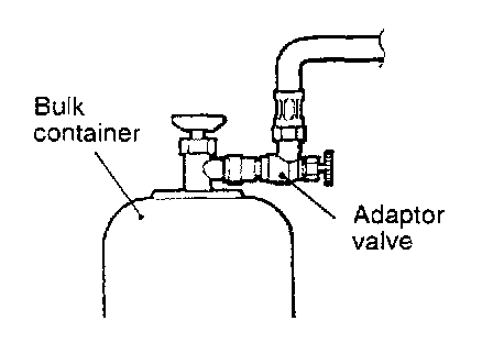
16. Turn the handle of the adaptor valve back all the way (valve closed), remove it from the gage manifold and install the bulk container.
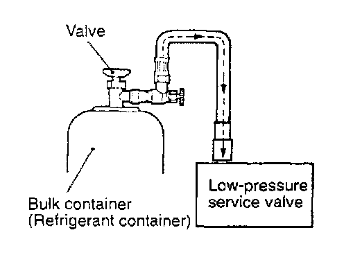
17. Open the valve of the bulk container.
18. Turn the handle of the charge valve back (valve open) and tighten the handle of the adaptor valve (valve open) to charge the system with refrigerant.
CAUTION: If the bulk container is inverted, liquid refrigerant may be drawn into the compressor, damaging it by hydraulic lock. Keep the bulk container upright to ensure that refrigerant is charged in gas state.
19. If the refrigerant is not drawn in, turn the handle of the adaptor valve back all the way (valve closed).
20. use a leak detector to check for gas leaks.
If a gas leak is detected, re-tighten the connections, and then repeat the charging procedure from evacuation in step (12).
CAUTION: A leak detector designed for R-134a should be used.
21. Start the engine.
22. Operate the air conditioning and set it to the lowest temperature (MAX. COOL).
23. Fix the engine speed at 1,500 r/min.
24. Tighten the handle of the adaptor valve (valve open) to charge the required volume of refrigerant.
CAUTION: If the bulk container is inverted, liquid refrigerant may be drawn into the compressor, damaging it by hydraulic lock. Keep the bulk container upright to ensure that refrigerant is charged in gas state.
25. After charging with refrigerant, turn the handle of the adaptor valve back all the way (valve closed).
26. Tighten the charge valve handle (valved closed). Disconnect the quick joint (for low pressure) from the low-pressure service valve.
Correcting Low Refrigerant Level When The Bulk Container Is Used
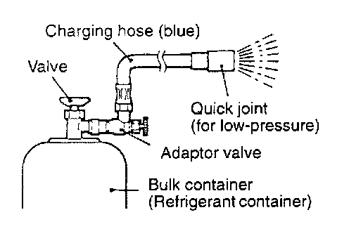
1. Install the adaptor valve with the handle turned all the way in (valve closed) to the charge valve.
2. Connect the charging hose (blue) to the adaptor valve.
3. Connect the charging hose (blue) to the quick joint (for low pressure).
4. Open the valve of the bulk container.
5. Turn the handle of the adaptor valve to bleed the air.
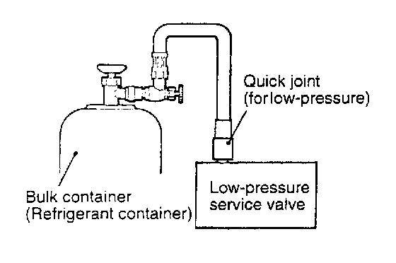
6. Connect the quick joint (for low pressure) to the low pressure service valve.
NOTE: The low-pressure service valve should be connected to the compressor.
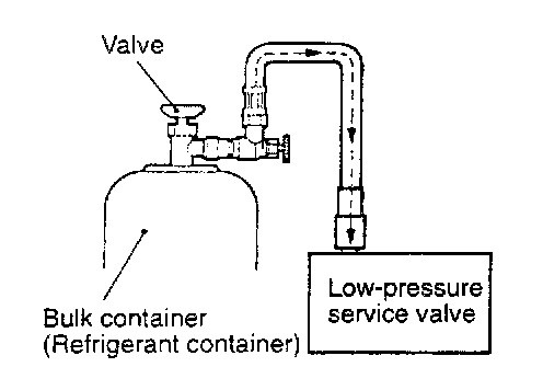
7. Start the engine.
8. Operate the air conditioning and set it to the lowest temperature (MAX. COOL).
9. Fix the engine speed at 1,500 r/min.
10. Tighten the handle of the adaptor valve (valve open) and replenish refrigerant while checking the quantity through the sight glass.
CAUTION: If the bulk container is inverted, liquid refrigerant may be draw into the compressor, damaging it by hydraulic lock. Keep the bulk container upright to ensure that refrigerant is charged in gas state.
11. After replenishing is completed, turn the handle of the adaptor valve all the way in (valve closed), and disconnect the quick joint.
Method By Using Refrigerant Recovery and Recycling Unit
Use the refrigerant recovery and recycling unit to refill with refrigerant.
NOTE: Refer to the refrigerant recovery and recycling unit instruction manual for operation of the unit.
DISCHARGING THE SYSTEM
Use the refrigerant recovery unit to discharge refrigerant gas from the system.
NOTE: Refer to the refrigerant recovery and recycling unit instruction manual for operation of the unit.
SUPPLYING OF OIL IN THE AIR CONDITIONING SYSTEM
Too little oil will provide inadequate compressor lubrication and cause a compressor failure. Too much oil will increase discharge air temperature.
When a 10PA15 compressor is installed at the factory, it contains 120 cu cm (4.1 fl.oz.) of refrigerant oil. While the air conditioning system is in operation, the oil is carried through the entire system by the refrigerant.
Some of this oil will trapped and retained in various parts of the system.
When the following system components are changed, it is necessary to add oil to the system to replace the oil being removed with the component.
Compressor oil: ND-OIL 8
Quantity:
Evaporator: 40 cu cm (1.4 fl.oz.)
Condenser: 40 cu cm (1.4 fl.oz.)
Suction hose: 10 cu cm (0.3 fl.oz.)
Receiver: 10 cu cm (0.3 fl.oz.)