Cranking Signal: Testing and Inspection
TROUBLESHOOTING HINTS:If the output of the park/neutral position switch is abnormal even though the results of the checking of the park/neutral position switch harness and of the component itself are normal, the cause is probably improper adjustment of the control cable.
INSPECTION
Using Scan Tool:

Ignition switch-ST

Park/neutral position switch
HARNESS INSPECTION
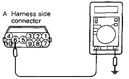
STEP 1. Measure the power supply voltage of the park/neutral position switch.
- Engine control module connector: Disconnected
- Park/neutral position switch connector: Disconnected
- Ignition switch: START
Voltage (V): Battery positive voltage
OK: GO TO STEP 2
NG: Check the power supply circuit.
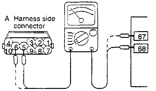
STEP 2. Check for continuity between the park/neutral position switch and the engine control module.
- Engine control module connector: Disconnected
- Park/neutral position switch connector: Disconnected
- Touch the ohmmeter probes to both ends of the harness.
OK: GO TO STEP 3
NG: Repair the harnesses. (A5 - 68, A6 - 67)
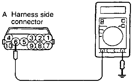
STEP 3. Measure the park/neutral position switch terminal input voltage.
- Engine control module connector: Connected
- Park/neutral position switch connector: Disconnected
- Ignition switch: ON
Voltage (V): Battery positive voltage
OK: STOP
NG: Replace the engine control module.
PARK/NEUTRAL POSITION SWITCH CHECK:
Refer to Transmission Position Switch/Sensor.