Component Tests and General Diagnostics
VOLUME AIR FLOW SENSOR INSPECTION PROCEDURE USING AN ANALYZERRequired Special Tool: MB991709 Test Harness
MEASUREMENT METHOD
1. Disconnect the volume air flow sensor connector and connect the test harness special tool (MB991709) in between. (All terminals should be connected.)
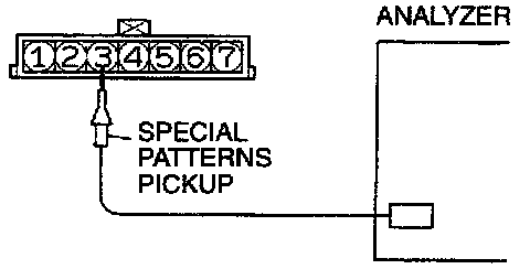
2. Connect the analyzer special pattern pickup to air flow sensor connector terminal 3.
ALTERNATE METHOD (Test harness not available)
1. Connect the analyzer special patterns pickup to ECM terminal 90.
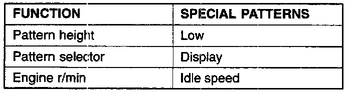
OBSERVATION CONDITIONS
STANDARD WAVE PATTERN
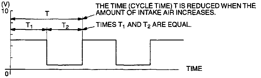
1. Observe that T1 and T2 remain equal when engine is raced.
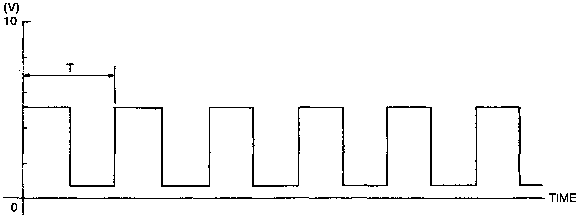
1. Check that cycle time T becomes shorter and the frequency increases when the engine speed is increased.
EXAMPLES OF ABNORMAL WAVE PATTERNS

Example 1
Cause of problem:
- Sensor interface malfunction.
Wave pattern characteristics:
- Rectangular wave pattern is output even when the engine is not started.
Example 2
Cause of problem:
- Damaged rectifier or vortex generation column.
Wave pattern characteristics:
- Unstable wave pattern with non-uniform frequency. An ignition leak will distort the wave pattern temporarily, even if the volume air flow sensor is normal.