Throttle Position Sensor: Adjustments
CLOSED THROTTLE POSITION SWITCH AND THROTTLE POSITION SENSOR ADJUSTMENTRequired Special Tools: MB991502 Scan Tool and/or MB991348 Test Harness Set
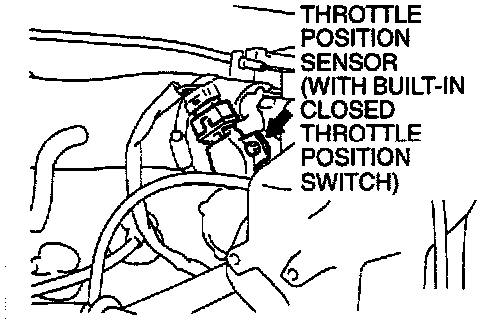
1. Connect the scan tool to the data link connector. When not using scan tool MB991502 proceed as follows.
(1) Disconnect the connector of the throttle position sensor.
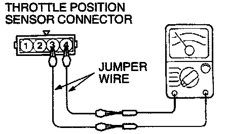
(2) Connect an ohmmeter between terminal 3 (closed throttle position switch) and 4 (sensor ground) by using jumper wires.
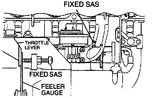
2. Insert a feeler gauge with a thickness of 0.45 mm (0.177 inch) between the fixed SAS and the throttle lever.
3. When using scan tool MB991502 turn the ignition switch "ON." (Do not start engine.) Observe operation of the closed throttle position switch.
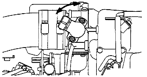
4. Loosen the throttle position sensor mounting bolt. Then turn the throttle position sensor body fully counterclockwise.
5. In this condition, make sure that the closed throttle position switch is "ON."
6. Slowly turn the throttle position sensor clockwise until the closed throttle position switch turns "OFF." Tighten the throttle position sensor installation bolt at that position. When using the scan tool, proceed to Step 8.
7. When not using scan tool MB991502 proceed as follows:
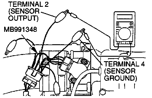
(1) Connect special tool MB991348 between the throttle position sensor connectors which have been disconnected. (Connect all terminals taking care not to mistake the terminal number.)
(2) Connect a digital voltmeter between the throttle position sensor terminal 2 (sensor output) and terminal 4 (sensor ground.)
(3) Turn the ignition switch "ON" (but do not start the engine).
8. Check the throttle position sensor output voltage.
Standard value: 400 - 1,000 mV
9. If there is a deviation from the standard value, check the throttle position sensor and the related harness.
10. Remove the feeler gauge.
Confirm the closed throttle position switch changed from "OFF" to "ON."
11. Turn the ignition switch "OFF."