California
HEATED OXYGEN SENSOR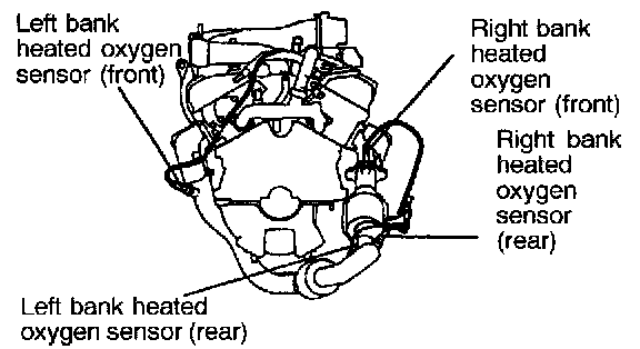
OPERATION
- The heated oxygen sensor functions to detect the concentration of oxygen in the exhaust gas; it converts those data to voltage, and inputs the resulting signals to the engine control module.
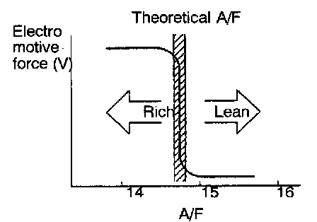
- If the air/fuel mixture ratio is richer than the theoretical air/fuel mixture ratio (i.e., if the concentration of oxygen in the exhaust gas is low), a voltage of approximately 1 V is output; if the air/fuel mixture ratio in leaner than the theoretical air/fuel mixture ratio (i.e., if the concentration is dense), a voltage of approximately 0 V is output.
- The engine control module, based upon those signals, regulates the amount of fuel injection so that the air/fuel mixture ratio becomes the theoretical air/fuel mixture ratio.
- Battery positive voltage is supplied, by way of the MFI relay, to the heated oxygen sensor heater. As a result, the sensor element is heated by the heater, so that the heated oxygen sensor shows excellent response even if the temperature of the exhaust gas is low.
TROUBLESHOOTING HINTS
Hint 1:
The exhaust gas purification performance will worsen it there is a malfunction of the heated oxygen sensor.
Hint 2:
If the heated oxygen sensor output voltage is outside the standard value even though the results of the checking of the heated oxygen sensor are normal, the cause is probably a malfunction of a component related to mixture control.
[Examples]
1. Malfunction of injector
2. Air is drawn into the intake manifold from a leaking gasket, etc.
3. Malfunction of volume air flow sensor, intake air temperature sensor, barometric pressure sensor or engine coolant temperature sensor
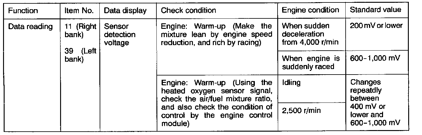
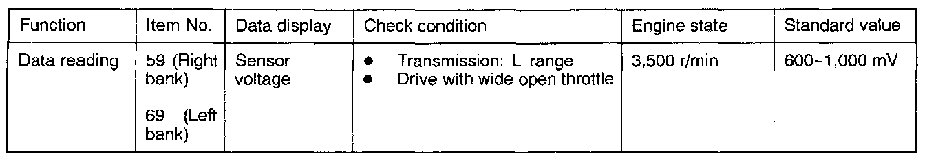
INSPECTION
Using Scan Tool
California:

HARNESS INSPECTION
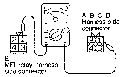
STEP 1. Check for continuity between heated oxygen sensor and MFI relay.
- MFI relay connector: Disconnected
- Heated oxygen sensor connector: Disconnected
NOTE: Insert the probes of the circuit tester into both ends of the harness.
OK: GO TO STEP 2
NG: Repair the harness. (A, B, C, D1 - E3)
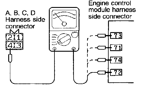
STEP 2. Check for an open-circuit, or a short-circuit to ground, between the engine control module and the heated oxygen sensor.
- Heated oxygen sensor connector: Disconnected
- Engine control module connector: Disconnected
OK: GO TO STEP 3
NG: Repair the harness. (A4 - 73, B4 - 71, C4 - 74, D4 - 72)
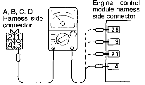
STEP 3. Check for an open-circuit, or a short-circuit to ground, between the engine control module and the heated oxygen sensor.
- Heated oxygen sensor connector: Disconnected
- Engine control module connector: Disconnected
OK: GO TO STEP 4
NG: Repair the harness. (A3 - 26, B3 - 3, C3 - 27, D3 - 4)
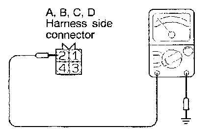
STEP 4. Check for continuity of the ground circuit.
- Heated oxygen sensor connector: Disconnected
OK: STOP
NG: Repair the harness. (A2, B2, C2, D2 - 49)
HEATED OXYGEN SENSOR CHECK
1. Disconnect the volume air flow sensor connectors.

2. Measure the resistance between terminal (5) and terminal (6).

Standard value:


3. Measure the resistance while heating the sensor using a hair drier.
4. If resistance does not decrease as heat increases or the resistance remains unchanged, replace the volume air flow sensor assembly.