Ignition Sw and Park/Neutral Switch Check
IGNITION SWITCH-ST AND PARK/NEUTRAL POSITION SWITCH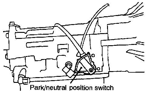

OPERATION
- The ignition switch-ST inputs HIGH signals to the engine control module during engine cranking. The engine control module regulates fuel injection during starting, etc. based on those signals.
- When the ignition switch is set to START, the battery positive voltage during engine cranking is applied to the engine control module by way of the ignition switch and the park/neutral position switch, and the engine control module thus detects the fact that the engine is cranking. Note that battery positive voltage is not applied to the engine control module if the selector lever is in a position other than P or N.
- The park/neutral position switch functions to convert the voltage to HIGH level or LOW level depending upon whether the selector lever is in the P or N position or is at some position other than P or N, and inputs the result to the engine control module. The engine control module, based upon those signals, then regulates the operation of the idle air control motor.
- Battery positive voltage inside the engine control module is applied via the resistance to the park/neutral position switch. When the selector lever is placed in the P or N position, continuity is created, between the engine control module's park/neutral position switch terminal and the ground via the starter motor, and the terminal voltage becomes low.
TROUBLESHOOTING HINTS
If the output of the park/neutral position switch is abnormal even though the results of the checking of the park/neutral position switch harness and of the component itself are normal, the cause is probably improper adjustment of the control cable.
INSPECTION
Using Scan Tool
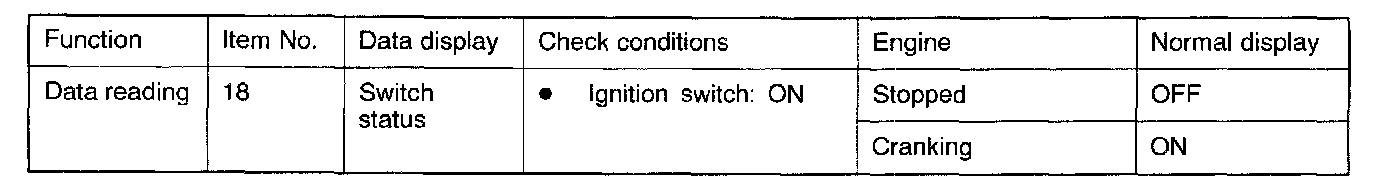
Ignition switch-ST
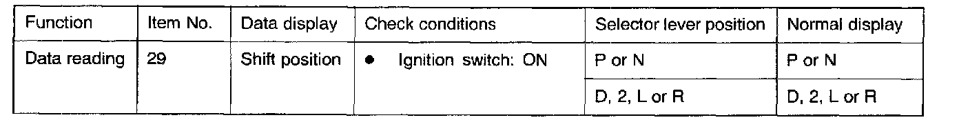
Park/neutral position switch
HARNESS INSPECTION
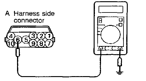
STEP 1. Measure the power supply voltage of the park/neutral position switch.
- Engine control module connector: Disconnected
- Park/neutral position switch connector: Disconnected
- Ignition switch: START
Voltage (V): Battery positive voltage
OK: GO TO STEP 2
NG: Check the power supply circuit.
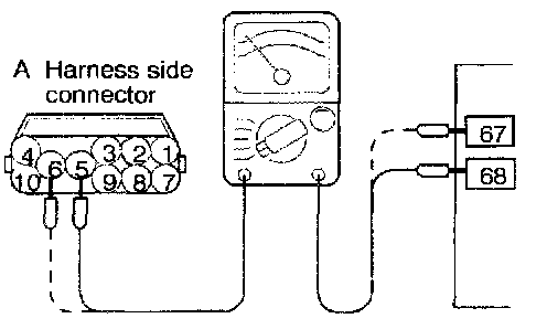
STEP 2. Check for continuity between the park/neutral position switch and the engine control module.
- Engine control module connector: Disconnected
- Park/neutral position switch connector: Disconnected
NOTE: Touch the ohmmeter probes to both ends of the harness.
OK: GO TO STEP 3
NG: Repair the harnesses. (A5 - 68, A6 - 67)
STEP 3. Measure the park/neutral position switch terminal input voltage.
- Engine control module connector: Connected
- Park/neutral position switch connector: Disconnected
- Ignition switch: ON
Voltage (V): Battery positive voltage
OK: STOP
NG: Replace the engine control module.
PARK/NEUTRAL POSITION SWITCH CHECK
Refer to On-vehicle Service.