Removal and Replacement
Part 1 Of 3:
Part 2 Of 3:

Part 3 Of 3:
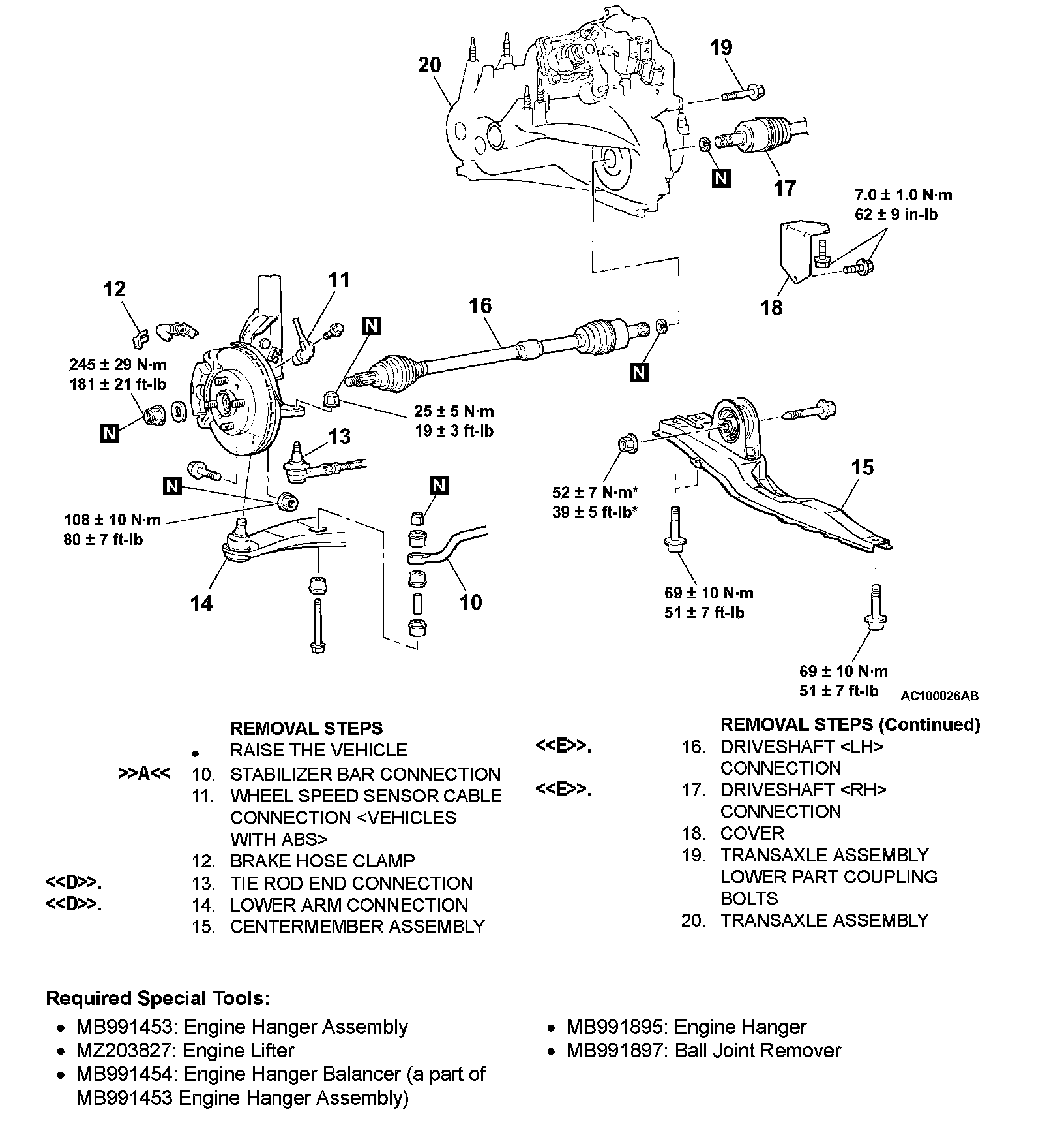
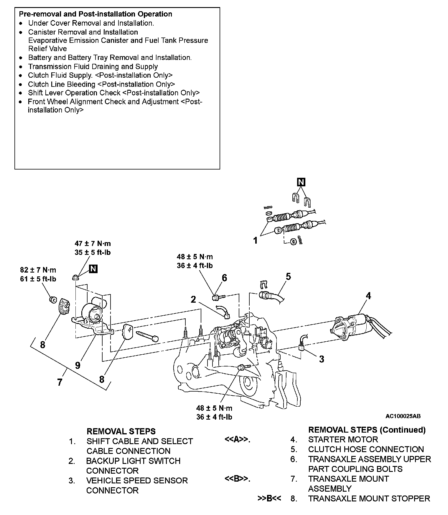
REMOVAL AND INSTALLATION
CAUTION: *: Indicates parts which should be temporarily tightened, and then fully tightened after installing the engine into the vehicle.
REMOVAL SERVICE POINTS
<> STARTER MOTOR REMOVAL
Remove the starter motor with the starter motor harness still connected and secure it inside the engine compartment.
<> TRANSAXLE MOUNT ASSEMBLY REMOVAL
Jack up the transaxle assembly gently with a garage jack, and then remove the transaxle mount bracket.
<
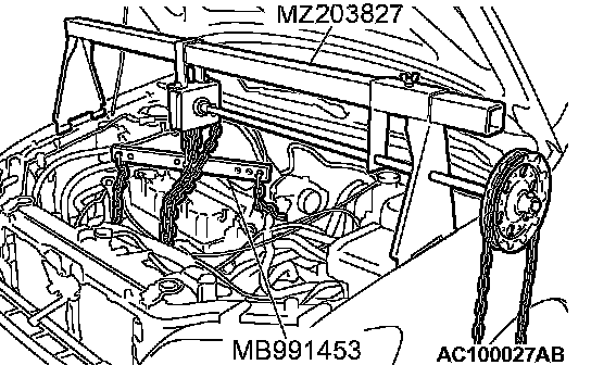
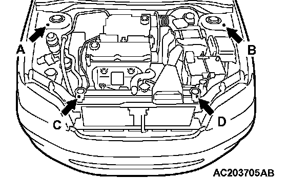
1. Set special tool MB991895 to the strut assembly mounting nuts (A and B) and the radiator support upper insulator mounting bolts (C and D), which are located in the engine compartment, as shown.
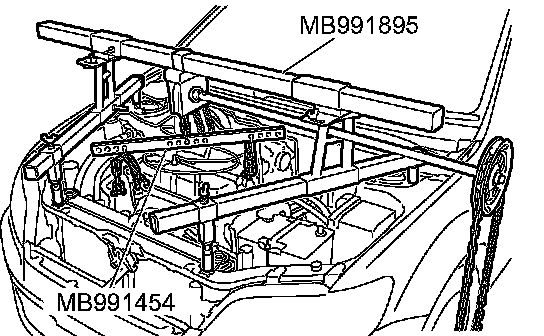
2. Set special tool MB991454 to hold the engine/transaxle assembly.
<
CAUTION:
^ Do not remove the nut from ball joint. Loosen it and use special tool MB991897 to avoid possible damage to ball joint threads.
^ Hang special tool MB991897 with cord to prevent them from falling.
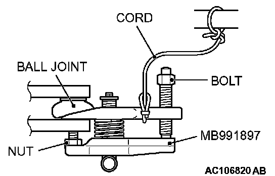
1. Install the special tool MB991897 as shown in the figure.
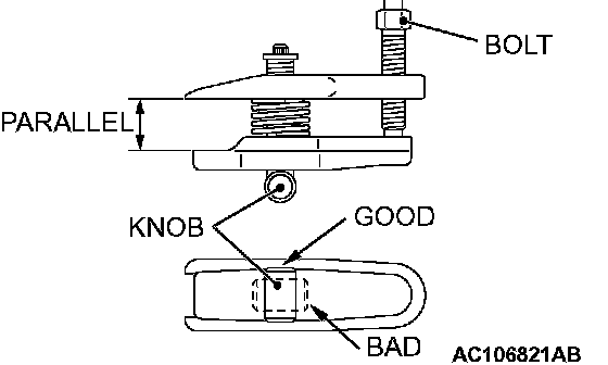
2. After turning the bolt and knob to adjust the insert arms of the special tool MB991897 in parallel, tighten the bolt by hand and confirm that the insert arms are parallel.
NOTE: When adjusting the insert arms in parallel, turn the knob in the direction shown in the figure.
<
CAUTION:
^ Do not pull on the driveshaft; doing so will damage the TJ; be sure to use a pry bar.
^ Do not insert a pry bar so deep as to damage the oil seal.
^ Do not damage the transaxle oil seal with the spline of the driveshaft.
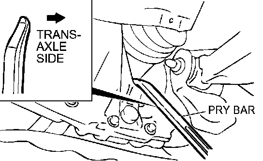
1. Insert a pry bar between the transaxle case and the driveshaft as shown to remove the driveshaft.
2. Suspend the removed driveshaft with a wire so that there are no sharp bends in any of the joints.
3. Use a shop towel to cover the transaxle case to avoid getting any foreign material get into it.
INSTALLATION SERVICE POINTS
>>A<< STABILIZER BAR INSTALLATION
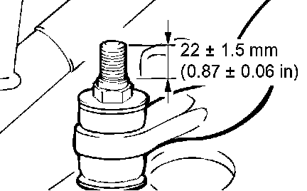
Tighten the self-locking nut so that the stabilizer bar mounting bolt protrudes as shown.
Standard value (A): 22 ± 1.5 mm (0.87 ± 0.06 inch)
>>B<< TRANSAXLE MOUNT STOPPER INSTALLATION
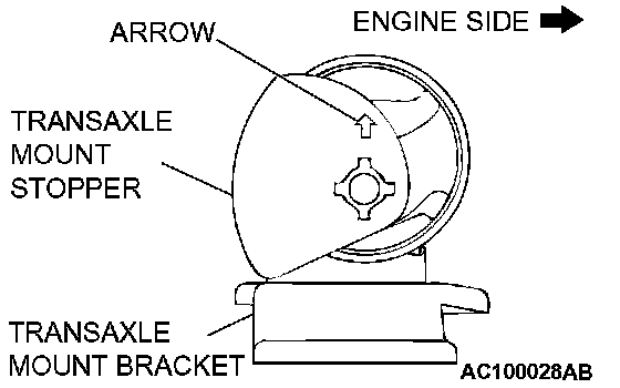
Install the transaxle mount stopper so that the arrow points as shown in the illustration.