Inspection Procedure 29
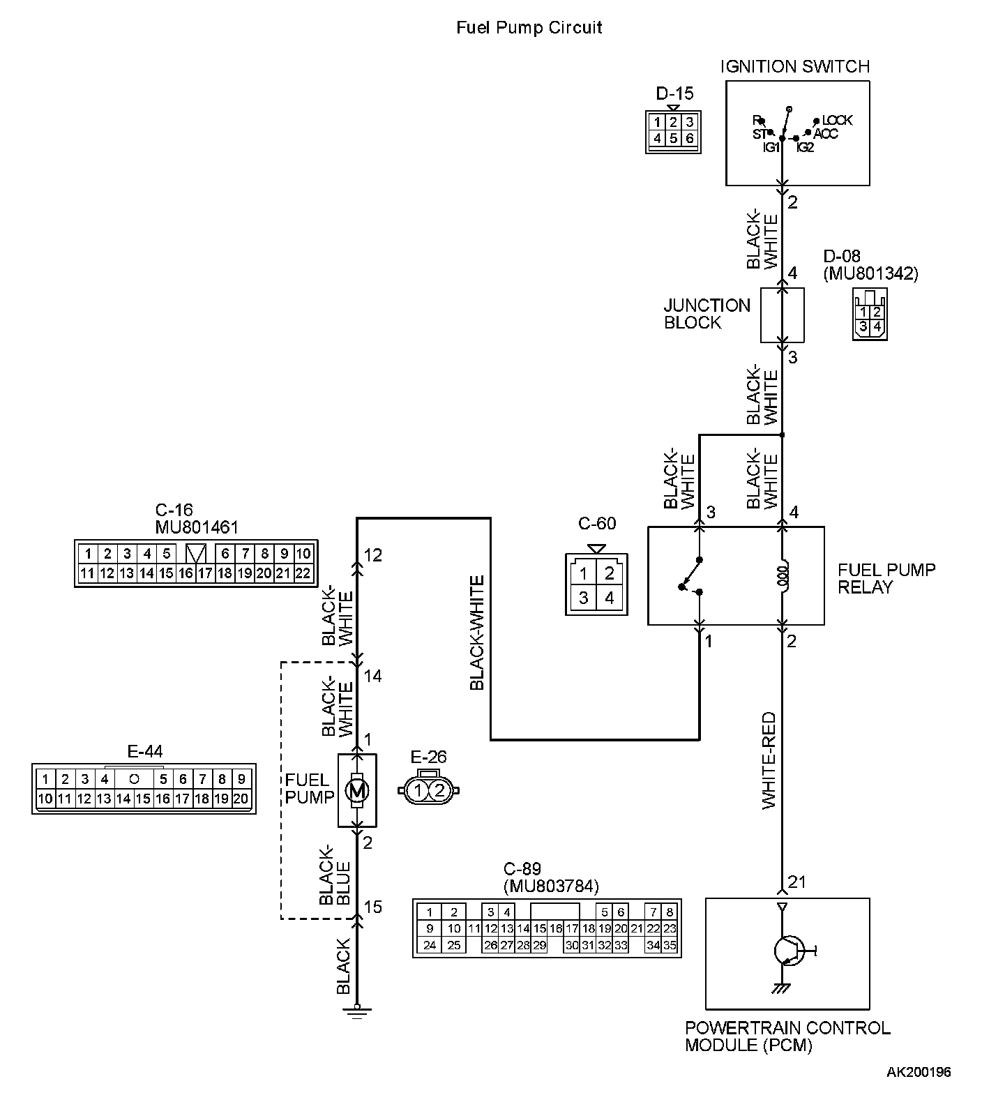
Fuel pump system.Fuel Pump Circuit Part 1:
Fuel Pump Circuit Part 2:
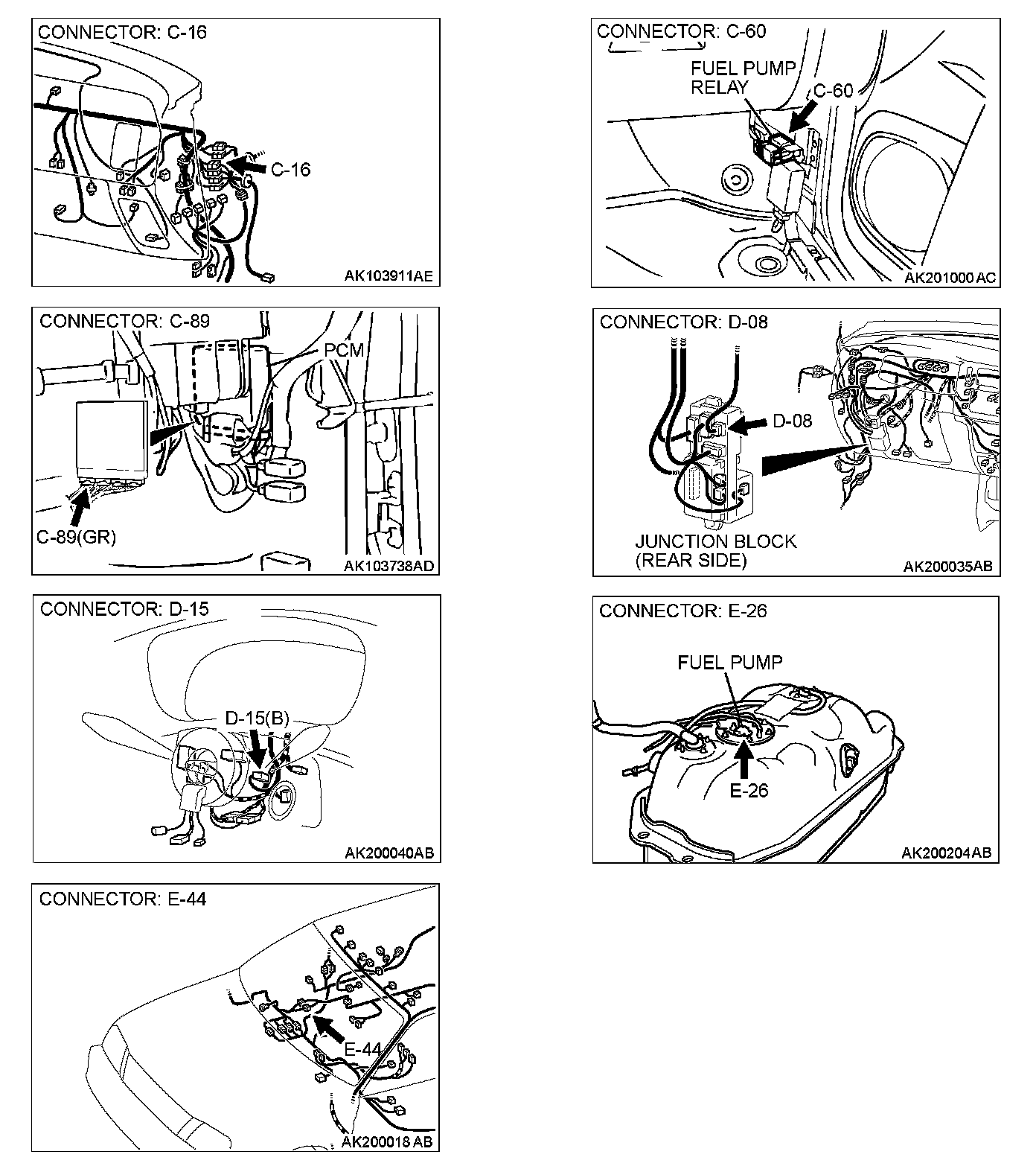
CIRCUIT OPERATION
- A battery positive voltage is applied on the fuel pump relay (terminals No. 3, No. 4) from the ignition switch-IG.
- During cranking and while the engine is running, the PCM turns the power transistor in the PCM "ON" to ground the fuel pump relay coil. With this, the fuel pump relay turns "ON" and the battery positive voltage is supplied to the fuel pump from the fuel pump relay (terminal No. 1).
TROUBLESHOOTING HINTS (The most likely causes for this code to be set are: )
- Malfunction of the fuel pump relay.
- Malfunction of the fuel pump.
- Improper connector contact, open or short-circuited harness wire.
- Malfunction of the PCM.
DIAGNOSIS
Required Special Tool:
- MB991502:Scan Tool (MUT-II)
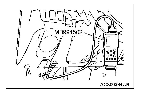
STEP 1. Using scan tool MB991502, check actuator test item 07: Fuel Pump.
CAUTION: To prevent damage to scan tool MB991502, always turn the ignition switch to the "LOCK" (OFF) position before connecting or disconnecting scan tool MB991502.
1. Connect scan tool MB991502 to the data link connector.
2. Turn the ignition switch to the "ON" position.
3. Set scan tool MB991502 to the actuator test mode for item 07, Fuel Pump.
- An operation sound of the fuel pump should be heard.
4. Turn the ignition switch to the "LOCK" (OFF) position.
Q: Is the fuel pump operating properly?
YES: That this malfunction is intermittent. Refer to How to Use Troubleshooting/Inspection Service Points.
NO: Go to Step 2.
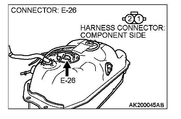
STEP 2. Check harness connector E-26 at fuel pump for damage.
Q: Is the harness connector in good condition?
YES: Go to Step 3.
NO: Repair or replace it. Refer to Harness Connector Inspection. Then confirm that the malfunction symptom is eliminated.
STEP 3 Check the fuel pump operation.
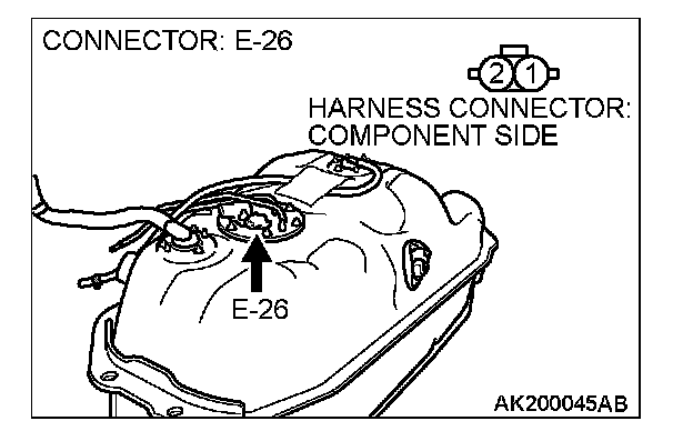
1. Disconnect fuel pump connector E-26.
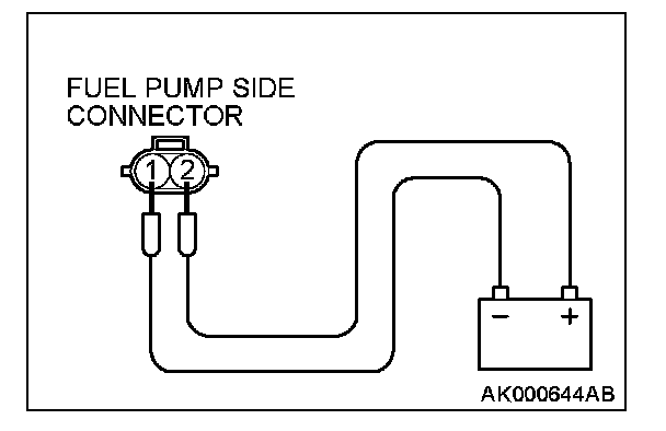
2. Use jumper wires to connect fuel pump connector terminal No. 1 to the positive battery terminal and terminal No. 2 to the negative battery terminal.
- An operating sound of the fuel pump should be heard.
Q: Is the fuel pump operating properly?
YES: Go to Step 4.
NO: Replace the fuel pump. Then confirm that the malfunction symptom is eliminated.
STEP 4. Check for continuity at fuel pump harness side connector E-26.
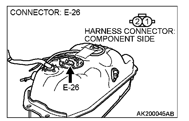
1. Disconnect the connector E-26 and measure at the harness side.
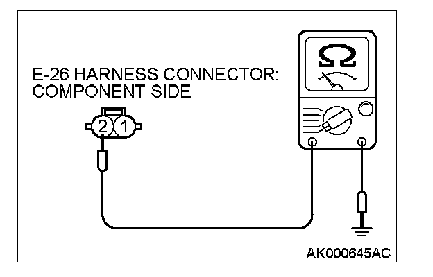
2. Check for the continuity between terminal No. 2 and ground.
- Should be less than 2 Ohms.
Q: Does continuity exist?
YES: Go to Step 5.
NO: Check harness connector E-44 at intermediate connector for damage, and repair or replace as required. Refer to, Harness Connector Inspection. If intermediate connector E-44 is in good condition, repair harness wire between fuel pump connector E-26 (terminal No. 2) and ground. Then confirm that the malfunction symptom is eliminated.
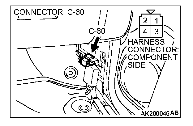
STEP 5. Check harness connector C-60 at fuel pump relay for damage.
Q: Is the harness connector in good condition?
YES: Go to Step 6.
NO: Repair or replace it. Refer to Harness Connector Inspection. Then confirm that the malfunction symptom is eliminated.
STEP 6. Check the fuel pump relay
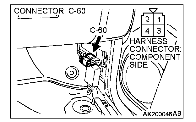
1. Remove the fuel pump relay.
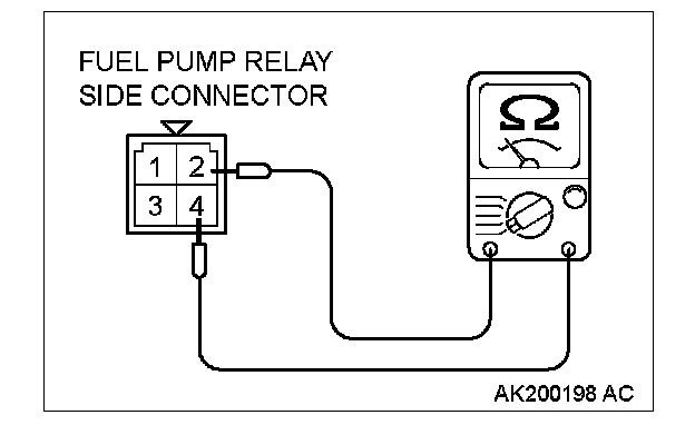
2. Check for continuity between the fuel pump relay terminal No. 2 and No. 4.
- There should be continuity (approximately 70 Ohms)
3. Use jumper wires to connect fuel pump relay terminal No. 4 to the positive battery terminal and terminal No. 2 to the negative battery terminal.
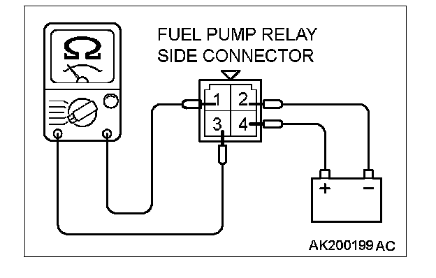
4. Check for continuity between the fuel pump relay terminal No. 1 and No. 3 while connecting and disconnecting the jumper wire at the negative battery terminal.
- Should be less than 2 Ohms. (Negative battery terminal connected)
- Should be open loop. (Negative battery terminal disconnected)
5. Install the fuel pump relay.
Q: Is the resistance normal?
YES: Go to Step 7.
NO: Replace the fuel pump relay. Then confirm that the malfunction symptom is eliminated
STEP 7. Measure the power supply voltage at fuel pump relay connector C-60.
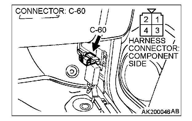
1. Disconnect the connector C-60 and measure at the harness side.
2. Turn the ignition switch to the "ON" position.
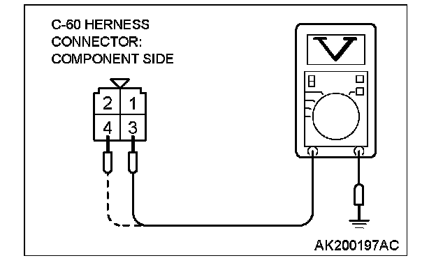
3. Measure the voltage between terminals No. 3, No. 4 and ground.
- Voltage should be battery positive voltage.
4. Turn the ignition switch to the "LOCK" (OFF) position.
Q: Is battery positive voltage (approximately 12 volts) present?
YES: Go to Step 8.
NO: Check harness connector D-08 at intermediate connector for damage, and repair or replace as required. Refer to, Harness Connector Inspection. If intermediate connector D-08 is in good condition, repair harness wire between ignition switch connector D-15 (terminal No. 2) and fuel pump relay connector C-60 (terminals No. 3, No. 4). Then confirm that the malfunction symptom is eliminated.
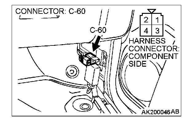
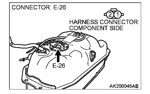
STEP 8. Check for open circuit and short circuit to ground and harness damage between fuel pump relay connector C-60 (terminal No. 1) and fuel pump connector E-26 (terminal No. 1).
NOTE: Check harness after checking intermediate connectors C-16 and E-44. If intermediate connectors C-16 and E-44 are damaged, repair or replace them. Refer to Harness Connector Inspection. Then check that the malfunction is eliminated.
Q: Is the harness wire in good condition?
YES: Go to Step 9.
NO: Repair it. Then confirm that the malfunction symptom is eliminated.
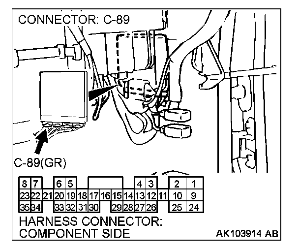
STEP 9. Check harness connector C-89 at PCM for damage.
Q: Is the harness connector in good condition?
YES: Go to Step 10.
NO: Repair or replace it. Refer to Harness Connector Inspection. Then confirm that the malfunction symptom is eliminated.
STEP 10. Measure the power supply voltage at PCM connector C-89.
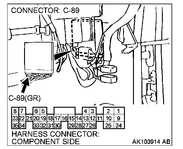
1. Disconnect the connector C-89 and measure at the harness side.
2. Turn the ignition switch to the "ON" position.
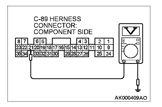
3. Measure the voltage between terminal No. 21 and ground.
- Voltage should be battery positive voltage.
4. Turn the ignition switch to the "LOCK" (OFF) position.
Q: Is battery positive voltage (approximately 12 volts) present?
YES: Replace the PCM. Then confirm that the malfunction symptom is eliminated.
NO: Repair harness wire between fuel pump relay connector C-60 (terminal No. 2) and PCM connector C-89 (terminal No. 21). Then confirm that the malfunction symptom is eliminated.