Inspection Procedure 30
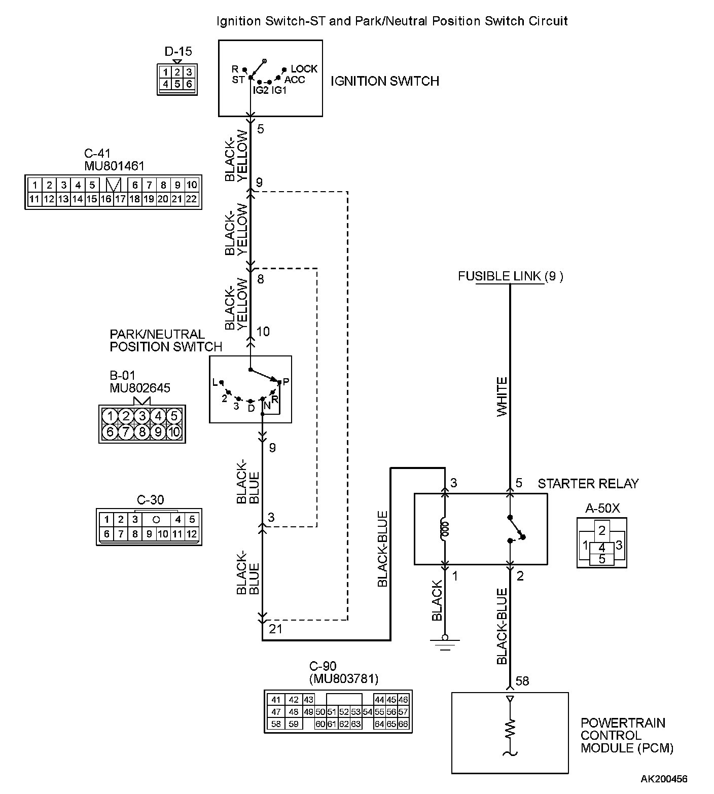
Ignition Switch-ST System and Park/Neutral Position Switch System.Ignition Switch-ST and Park/Neutral Position Switch Circuit Part 1:
Ignition Switch-ST and Park/Neutral Position Switch Circuit Part 2:
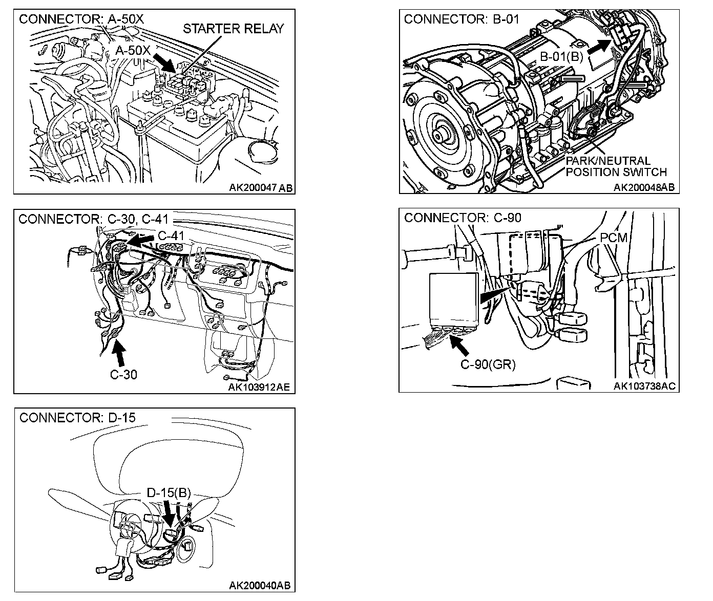
COMMENT
- If the selector lever is moved to "P" or "N" range and the ignition switch is turned to "START" position, battery positive voltage is supplied to PCM (terminal No. 58) through the starter relay. Because of this, the PCM detects that the engine is cranking.
TROUBLESHOOTING HINTS (The most likely caused for this code to be set are: )
- Malfunction of the ignition switch.
- Malfunction of the park/neutral position switch.
- Improper connector contact, open circuit or short-circuit in the harness wire.
- Malfunction of the starter relay
- Malfunction of the PCM.
DIAGNOSIS
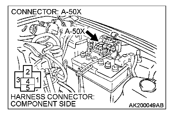
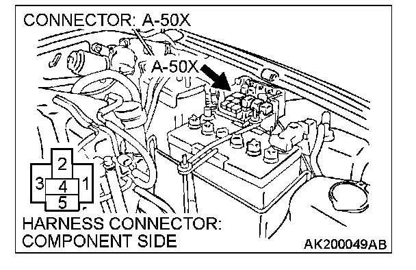
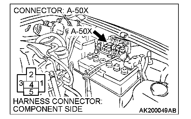
STEP 1. Check connector A-50X at starter relay for damage.
Q: Is the connector in good condition?
YES: Go to Step 2.
NO: Repair or replace it. Refer to Harness Connector Inspection. Then confirm that the malfunction symptom is eliminated.
STEP 2. Check the starter relay.
Refer to Starting System - On-vehicle Service - Starter relay check.
Q: Are there any abnormalities?
YES: Go to Step 3.
NO: Repair or replace it. Then confirm that the malfunction symptom is eliminated.
STEP 3. Measure the power supply voltage at starter relay connector A-50X.
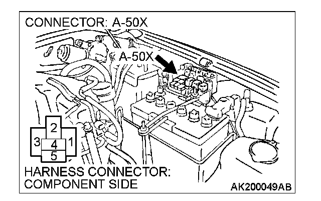
1. Disconnect the connector A-50X and measure at the harness side.
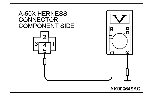
2. Measure the voltage between terminal No. 5 and ground.
- Voltage should be battery positive voltage.
Q: Is battery positive voltage (approximately 12 volts) present?
YES: Go to Step 4.
NO: Repair harness wire between fusible link (9) and starter relay connector A-50X (terminal No. 5) because of open circuit. Then confirm that the malfunction symptom is eliminated.
STEP 4. Check for continuity at starter relay harness side connector A-50X.
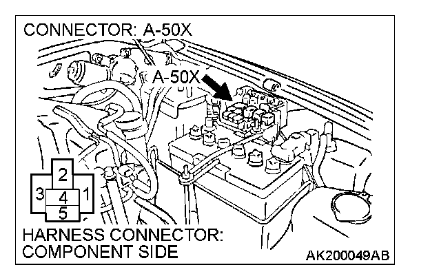
1. Disconnect the connector A-50X and measure at the harness side.
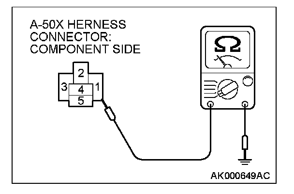
2. Check for the continuity between terminal No. 1 and ground.
- Should be less than 2 Ohms.
Q: Does continuity exist?
YES: Go to Step 5.
NO: Repair harness wire between starter relay connector A-50X (terminal No. 1) and ground. Then confirm that the malfunction symptom is eliminated.
STEP 5. Measure the power supply voltage at starter relay connector A-50X.
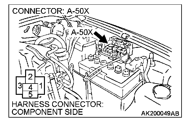
1. Disconnect the connector A-50X and measure at the harness side.
2. Turn the ignition switch to the "START" position.
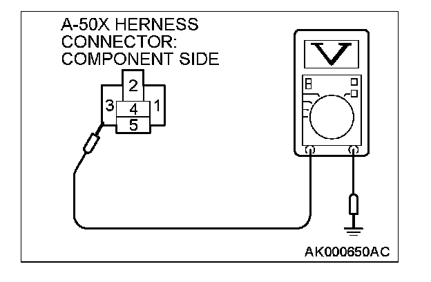
3. Measure the voltage between terminal No. 3 and ground.
- Voltage should be battery positive voltage. (Selector lever P or N range) (4) Turn the ignition switch to the "LOCK" (OFF) position.
Q: Is battery positive voltage (approximately 12 volts) present?
YES: Go to Step 10.
NO: Go to Step 6.
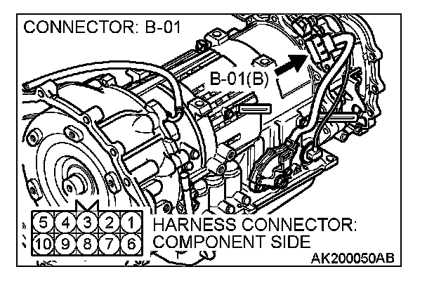
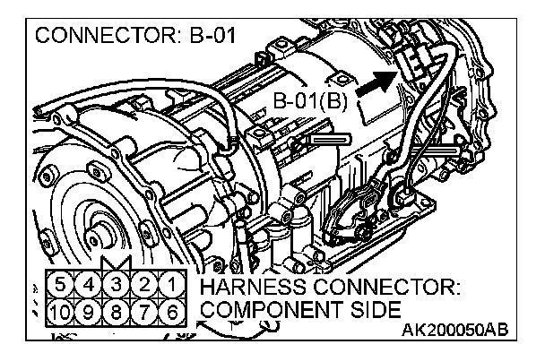
STEP 6. Check connector B-01 at park/neutral position switch for damage.
Q: Is the connector in good condition?
YES: Go to Step 7.
NO: Repair or replace it. Refer to Harness Connector Inspection. Then confirm that the malfunction symptom is eliminated.
STEP 7. Check the park/neutral position switch.
Refer to On-vehicle Service - Essential Service - Park/neutral position switch continuity check.
Q: Are there any abnormalities?
YES: Go to Step 8.
NO: Repair or replace it. Then confirm that the malfunction symptom is eliminated.
STEP 8. Measure the power supply voltage at park/neutral position switch connector B-01.
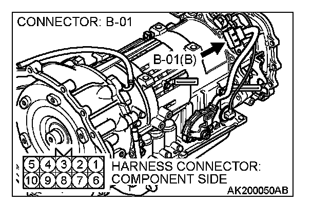
1. Disconnect the connector B-01 and measure at the harness side.
2. Turn the ignition switch to the "START" position.
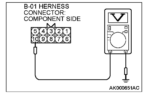
3. Measure the voltage between terminal No. 10 and ground.
- Voltage should be battery positive voltage.
4. Turn the ignition switch to the "LOCK" (OFF) position.
Q: Is battery positive voltage (approximately 12 volts) present?
YES: Go to Step 9.
NO: Check connector C-30 and C-41 at intermediate connector for damage, and repair or replace as required. Refer to Harness Connector Inspection. If intermediate connector are in good condition, repair harness wire between ignition switch connector D-15 (terminal No. 5) and park/ neutral position switch connector B-01 (terminal No. 10) because of open circuit. Then confirm that the malfunction symptom is eliminated.
STEP 9. Check for open circuit and short circuit to ground and harness damage between park/neutral position switch connector B-01 (terminal No. 9) and starter relay connector A-50X (terminal No. 3).
NOTE: Check harness after checking intermediate connector C-30 and C-41. If intermediate connector are damaged, repair or replace them. Refer to Harness Connector Inspection. Then confirm that the malfunction symptom is eliminated.
Q: Is the harness wire in good condition?
YES: Go to Step 10.
NO: Repair it. Then confirm that the malfunction symptom is eliminated.
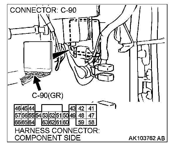
STEP 10. Check connector C-90 at PCM for damage.
Q: Is the connector in good condition?
YES: Go to Step 11.
NO: Repair or replace it. Refer to Harness Connector Inspection. Then confirm that the malfunction symptom is eliminated.
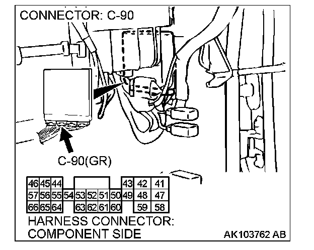
STEP 11. Check for open circuit and short circuit to ground and harness damage between starter relay connector A-50X (terminal No. 2) and PCM connector C-90 (terminal No. 58).
Q: Is the harness wire in good condition?
YES: Replace the PCM. Then confirm that the malfunction symptom is eliminated.
NO: Repair it. Then confirm that the malfunction symptom is eliminated.