Part 2
STEP 15. Check the A/C-ECU for short circuit. Measure the resistance at A/C-ECU connector C-16.
CAUTION: A digital multimeter should be used. For details refer to "Service Precautions".
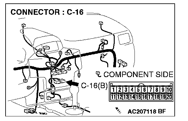
1. Disconnect A/C-ECU connector C-16, and measure the resistance at the equipment side of A/C-ECU connector C-16
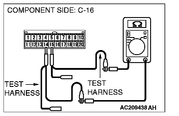
2. Measure the resistance between A/C-ECU connector terminals 14 and 15.
OK: 1 kOhm or more
Q: Does the resistance measure 1 kOhm or more?
YES:
NO:
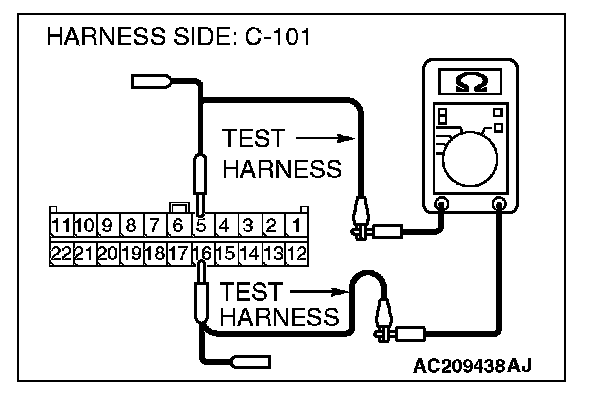
STEP 16. Check the CAN_L and H lines (communication lines including the middle-grade multi-center display) between joint connector 4. and the middle-grade multi-center display for short circuit. Measure the resistance at joint connector 4. C-101.
CAUTION: A digital multimeter should be used. For details refer to "Service Precautions".
CAUTION: The test wiring harness should be used. For details refer to "Service Precautions".
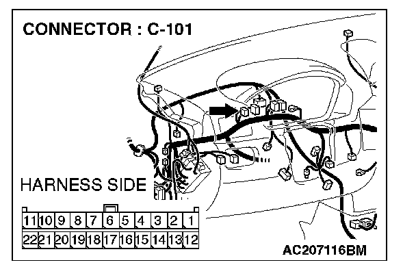
1. Disconnect joint connector 4. C-101, and measure the resistance at the wiring harness side of joint connector 4. C-101.
2. Turn the ignition switch to the "LOCK" (OFF) position.
CAUTION: Disconnect the negative battery terminal. For details refer to "Service Precautions".
3. Disconnect the negative battery terminal.
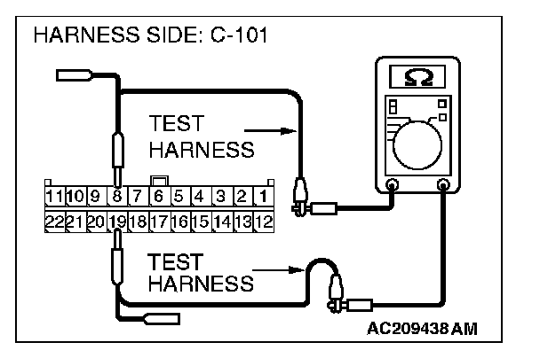
4. Measure the resistance between joint connector 4. terminals 8 and 19.
OK: 1 kOhm or more
Q: Does the resistance measure 1 kOhm or more?
YES:
NO:
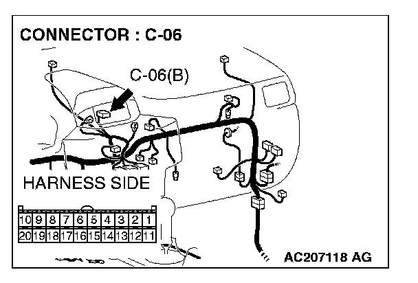
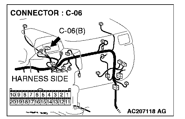
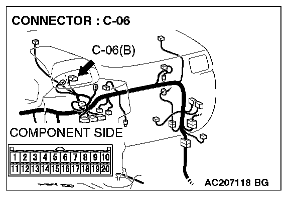
STEP 17. Check multi-center display unit (middle-grade type) connector C-06 for loose, corroded or damaged terminals, or terminals pushed back in the connector.
CAUTION: The strand end of the twist wire should be within 10 cm from the connector. For details refer to "Service Precautions".
Q: Is multi-center display unit (middle-grade type) connector C-06 in good condition?
YES: Go to Step 18.
NO: Repair the damaged parts.
STEP 18. Check the CAN_L and H lines (communication lines only) between joint connector 4. and the middle-grade multi-center display for short circuit. Measure the resistance at joint connector 4. C-101.
CAUTION: A digital multimeter should be used. For details refer to "Service Precautions".
CAUTION: The test wiring harness should be used. For details refer to "Service Precautions".
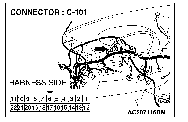
1. Disconnect joint connector 4. C-101 and multi-center display unit (middle-grade type) connector C-06, and measure the resistance at the wiring harness side of joint connector 4. C-101.
2. Turn the ignition switch to the "LOCK" (OFF) position.
CAUTION: Disconnect the negative battery terminal. For details refer to "Service Precautions".
3. Disconnect the negative battery terminal.
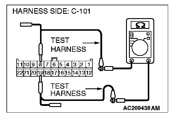
4. Measure the resistance between joint connector 4. terminals 8 and 19.
OK: 1 kOhm or more
CAUTION: Strictly observe the specified wiring harness repair procedure. For details refer to "Precautions On How To Repair The CAN Bus Lines".
Q: Does the resistance measure 1 kOhm or more?
YES:
NO:
STEP 19. Check the multi-center display unit (middle-grade type) for short circuit. Measure the resistance at multi-center display unit (middle-grade type) connector C-06.
CAUTION: A digital multimeter should be used. For details refer to "Service Precautions".
1. Disconnect multi-center display unit (middle-grade type) connector C-06, and measure the resistance at the equipment side of multi-center display unit (middle-grade type) connector C-06.
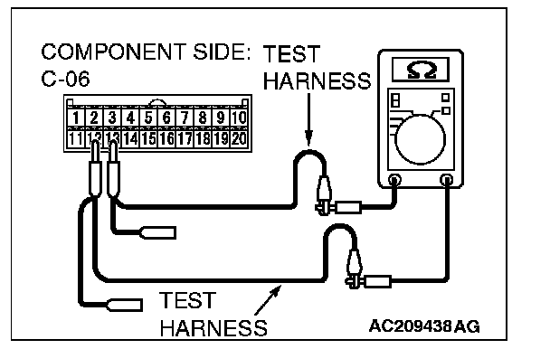
2. Measure the resistance between the multi-center display unit (middle-grade type) connector terminals 12 and 13.
OK: 1 kOhm or more
Q: Does the resistance measure 1 kOhm or more?
YES:
NO:
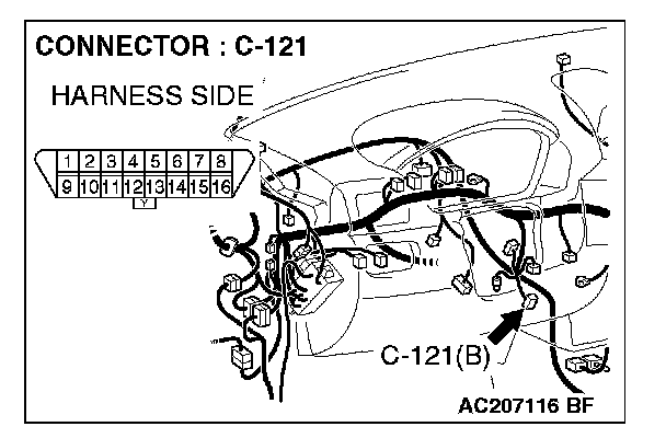
STEP 20. Check data link connector C-121 for loose, corroded or damaged terminals, or terminals pushed back in the connector.
CAUTION: The strand end of the twist wire should be within 10 cm from the connector. For details refer to "Service Precautions".
Q: Is data link connector C-121 in good condition?
YES: Go to Step 21.
NO: Repair the damaged parts.
STEP 21. Check the CAN_L and H lines (communication lines only) between joint connector 4. and the data link connector for short circuit. Measure the resistance at joint connector 4. C-101.
CAUTION: A digital multimeter should be used. For details refer to "Service Precautions".
CAUTION: The test wiring harness should be used. For details refer to "Service Precautions".
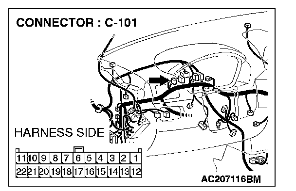
1. Disconnect joint connector 4. C-101, and measure the resistance at the wiring harness side of joint connector 4. C-101.
2. Turn the ignition switch to the "LOCK" (OFF) position.
CAUTION: Disconnect the negative battery terminal. For details refer to "Service Precautions".
3. Disconnect the negative battery terminal.
4. Measure the resistance between joint connector 4. terminals 5 and 16.
OK: 1 kOhm or more
Q: Does the resistance measure 1 kOhm or more?
YES:
NO:
STEP 22. Check the CAN_L and H lines (communication lines only) between joint connector 4. and the intermediate connector for short circuit. Measure the resistance at joint connector 4. C-101.
CAUTION: A digital multimeter should be used. For details refer to "Service Precautions".
CAUTION: The test wiring harness should be used. For details refer to "Service Precautions".
1. Disconnect intermediate connector C-31 and joint connector 4. C-101, and measure the resistance at the wiring harness side of joint connector 4. C-101.
2. Turn the ignition switch to the "LOCK" (OFF) position.
CAUTION: Disconnect the negative battery terminal. For details refer to "Service Precautions".
3. Disconnect the negative battery terminal.
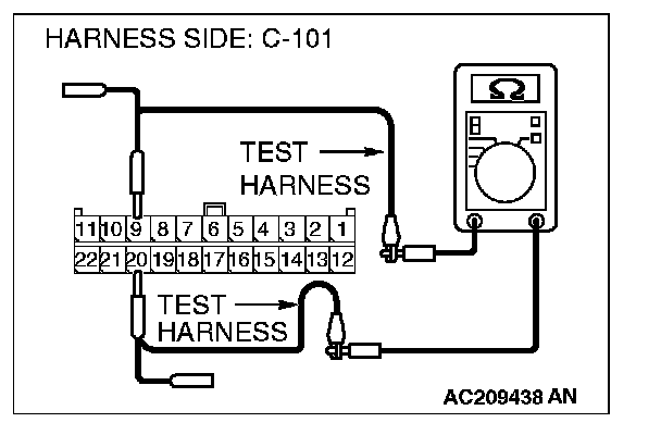
4. Measure the resistance between joint connector 4. terminals 9 and 20.
OK: 1 kOhm or more
CAUTION: Strictly observe the specified wiring harness repair procedure. For details refer to "Precautions On How To Repair The CAN Bus Lines".
Q: Does the resistance measure 1 kOhm or more?
YES:
NO:
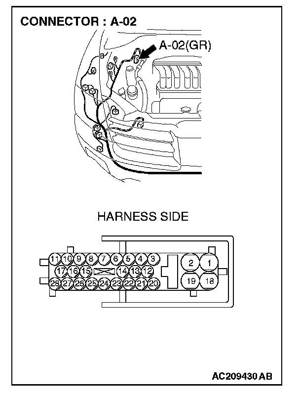
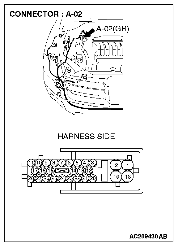
STEP 23. Check ABS-ECU connector A-02 for loose, corroded or damaged terminals, or terminals pushed back in the connector.
CAUTION: The strand end of the twist wire should be within 10 cm from the connector. For details refer to "Service Precautions".
Q: Is ABS-ECU connector A-02 in good condition?
YES: Go to Step 24.
NO: Repair the damaged parts.
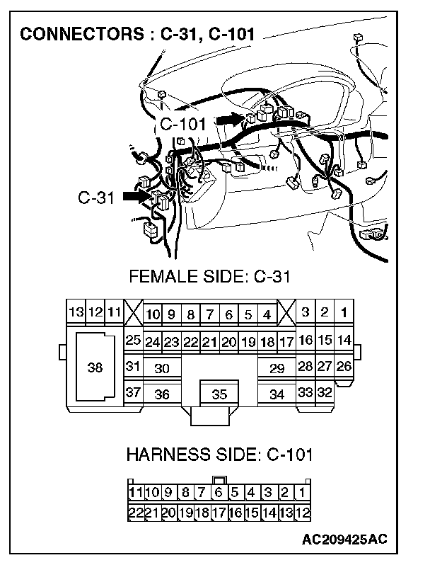
STEP 24. Check the CAN_L and H lines (communication lines only) between the ABS-ECU connector and the intermediate connector for short circuit. Measure the resistance at intermediate connector C-31.
CAUTION: A digital multimeter should be used. For details refer to "Service Precautions".
CAUTION: The test wiring harness should be used. For details refer to "Service Precautions".
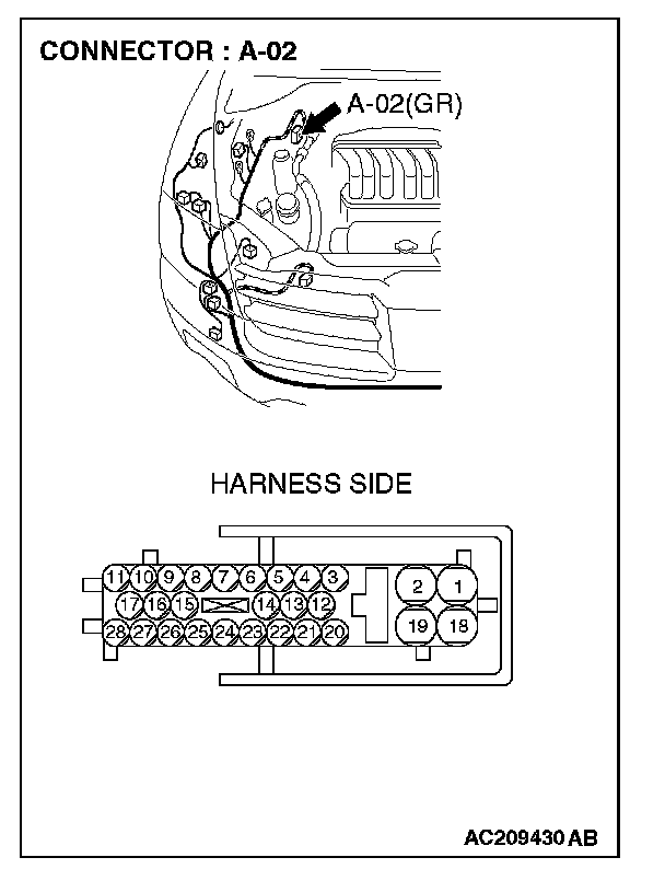
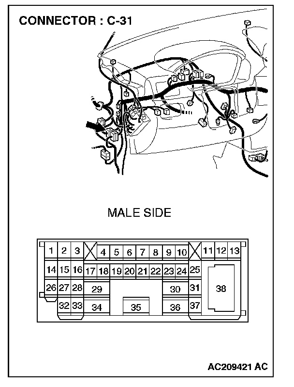
1. Disconnect intermediate connector C-31 and ABS-ECU connector A-02, and measure the resistance at the male side of intermediate connector C-31 (at front wiring harness side).
2. Turn the ignition switch to the "LOCK" (OFF) position.
CAUTION: Disconnect the negative battery terminal. For details refer to "Service Precautions".
3. Disconnect the negative battery terminal.
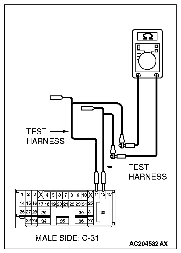
4. Measure the resistance between intermediate connector C-31 terminals 11 and 12.
OK: 1 kOhm or more
Q: Does the resistance measure 1 kOhm or more?
YES:
NO:
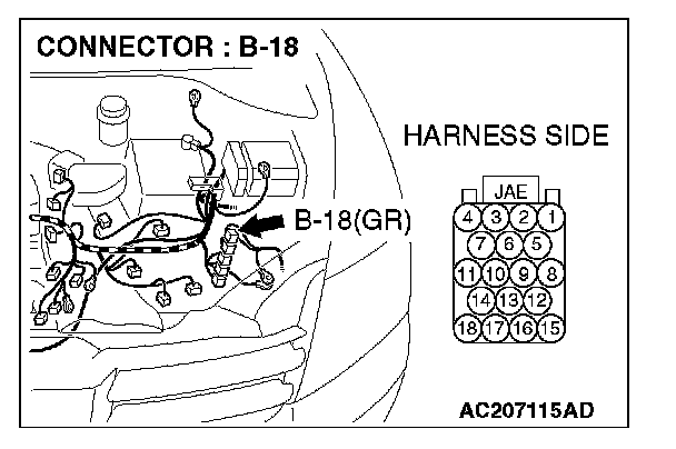
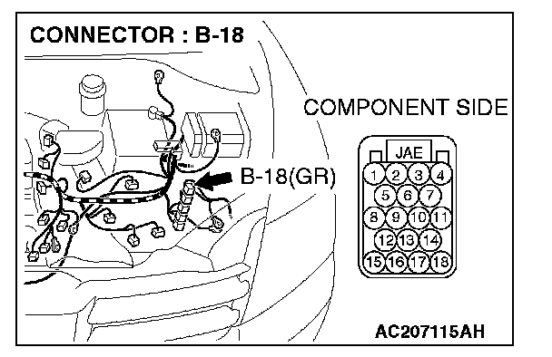
STEP 25. Check powertrain control module connector B-18 for loose, corroded or damaged terminals, or terminals pushed back in the connector.
CAUTION: The strand end of the twist wire should be within 10 cm from the connector. For details refer to "Service Precautions".
Q: Is powertrain control module connector B-18 in good condition?
YES: Go to Step 26.
NO: Repair the damaged parts.
STEP 26. Check the CAN_L and H lines (communication lines only) between the powertrain control module connector and the ABS-ECU connector for short circuit. Measure the resistance at powertrain control module connector B-18.
CAUTION: A digital multimeter should be used. For details refer to "Service Precautions".
CAUTION: The test wiring harness should be used. For details refer to "Service Precautions".
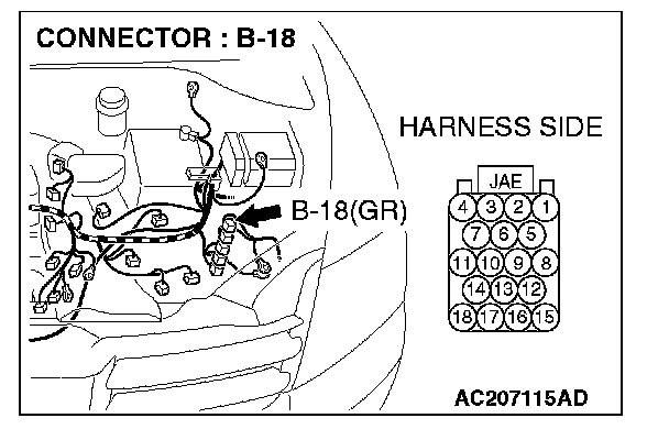
1. Disconnect powertrain control module connector B-18 and ABS-ECU connector A-02, and measure the resistance at the harness side of powertrain control module connector B-18.
2. Turn the ignition switch to the "LOCK" (OFF) position.
CAUTION: Disconnect the negative battery terminal. For details refer to "Service Precautions".
3. Disconnect the negative battery terminal.
4. Measure the resistance between powertrain control module connector terminals 17 and 18.
OK: 1 kOhm or more
CAUTION: Strictly observe the specified wiring harness repair procedure. For details refer to "Precautions On How To Repair The CAN Bus Lines".
Q: Does the resistance measure 1 kOhm or more?
YES:
NO:
STEP 27. Check the ABS-ECU for short circuit. Measure the resistance at ABS-ECU connector A-02.
CAUTION: A digital multimeter should be used. For details refer to "Service Precautions".
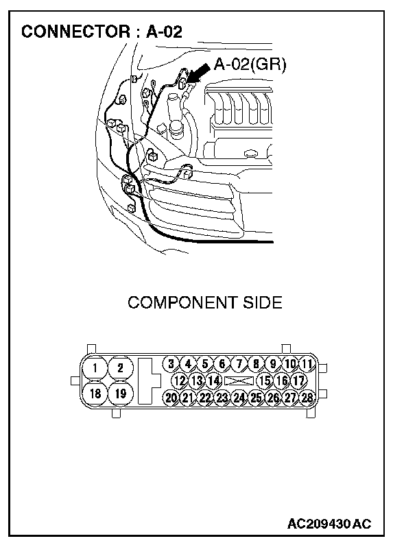
1. Disconnect ABS-ECU connector A-02, and measure the resistance at the equipment side of ABS-ECU connector A-02.
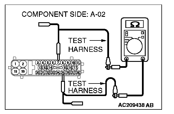
2. Measure the resistance between ABS-ECU connector terminals 7 and 25.
OK: 1 kOhm or more
Q: Does the resistance measure 1 kOhm or more?
YES:
NO:
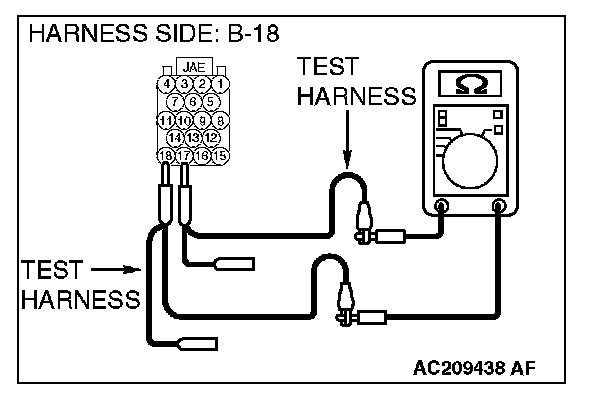
STEP 28. Check the powertrain control module for short circuit. Measure the resistance at powertrain control module connector B-18.
CAUTION: A digital multimeter should be used. For details refer to "Service Precautions".
1. Disconnect powertrain control module connector B-18, and measure the resistance at the equipment side of powertrain control module connector B-18.
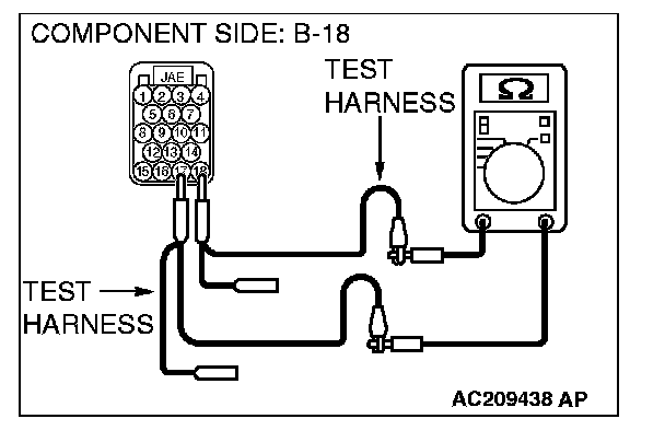
2. Measure the resistance between powertrain control module connector terminals 17 and 18.
OK: 120 ± 20 Ohms
Q: Does the resistance measure 120 ± 20 Ohms?
YES:
NO: