Diagnostic Item 13
DIAGNOSTIC ITEM 13: Diagnose terminator resistors at both ends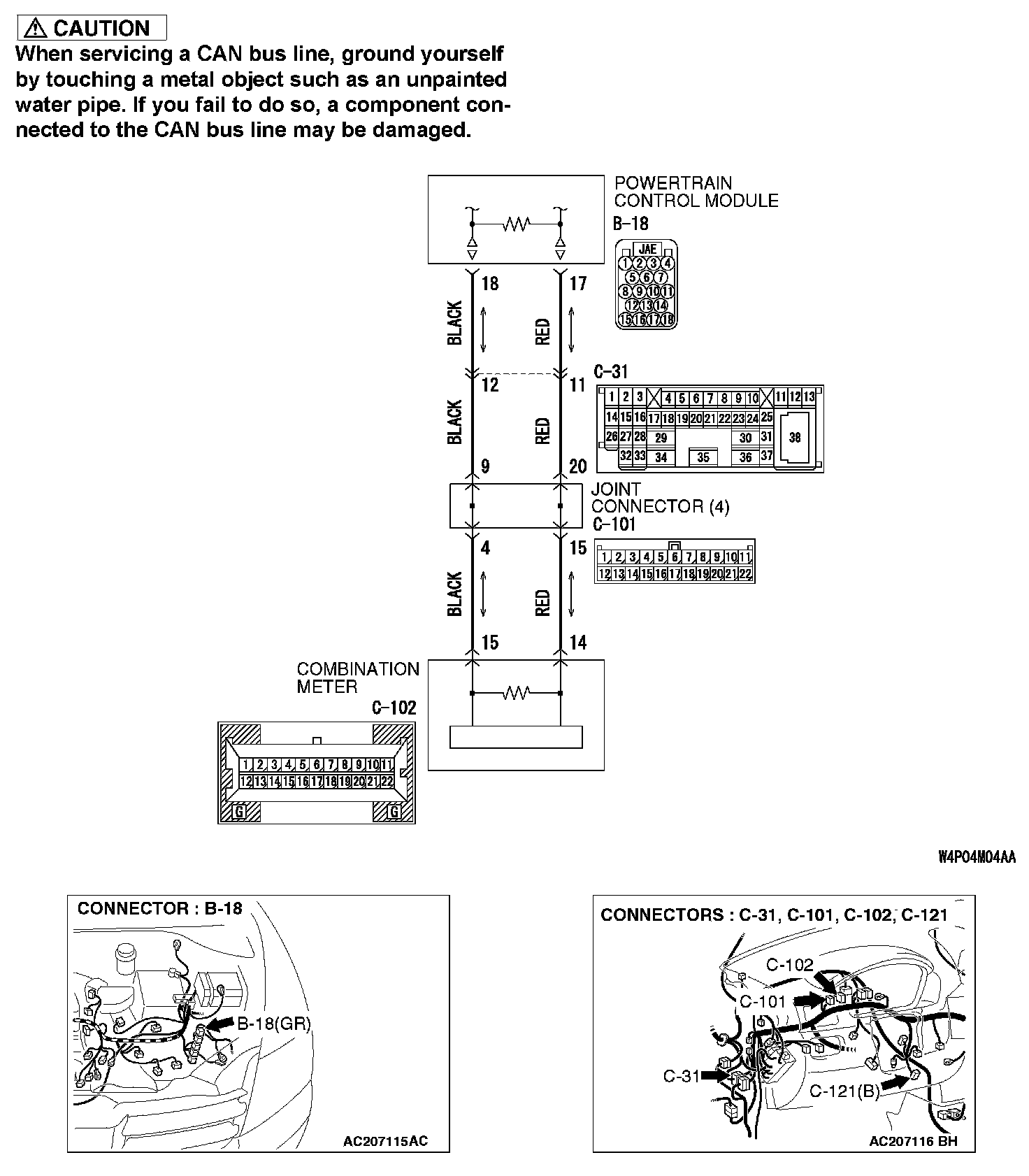
TROUBLE JUDGMENT
The terminator resistors at both ends of CAN bus lines may be damaged, when the resistance between the CAN bus lines (CAN_L and H lines) is more than 2 Ohms.
COMMENTS ON TROUBLE SYMPTOM
The CAN bus line harness wires or connectors may be damaged (open circuit may be present on CAN_L or CAN_H line between the data link connector and CAN main bus lines, or CAN main bus lines may be open at both sides), or the combination meter and the powertrain control module may be defective.
TROUBLESHOOTING HINTS
- The wiring harness or connectors may have loose, corroded, or damaged terminals, or terminals pushed back in the connector
- The combination meter may be defective
- The powertrain control module may be defective
DIAGNOSIS
Required Special Tool:
- MB991223: Harness Set
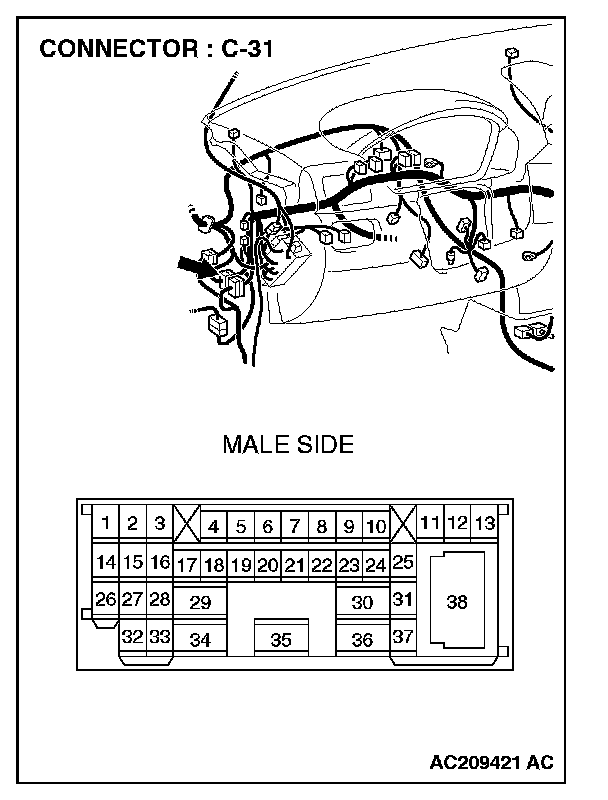
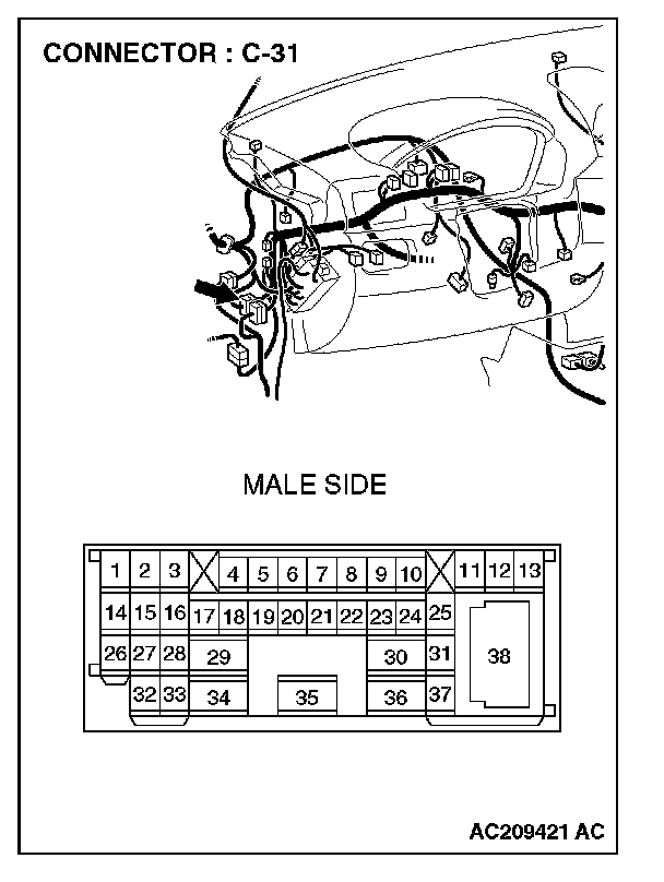
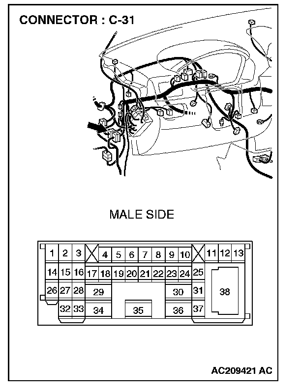
STEP 1. Check intermediate connector C-31 for loose, corroded or damaged terminals, or terminals pushed back in the connector.
CAUTION: The strand end of the twist wire should be within 10 cm from the connector. For details refer to "Service Precautions".
Q: Is intermediate connector C-31 in good condition?
YES: Go to Step 2.
NO: Repair the damaged parts.
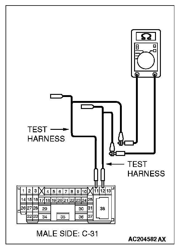
STEP 2. Check the instrument panel wiring harness side CAN bus lines (communication line including the combination meter). Measure the resistance at intermediate connector C-31.
CAUTION: A digital multimeter should be used. For details refer to "Service Precautions".
CAUTION: The test wiring harness should be used. For details refer to "Service Precautions".
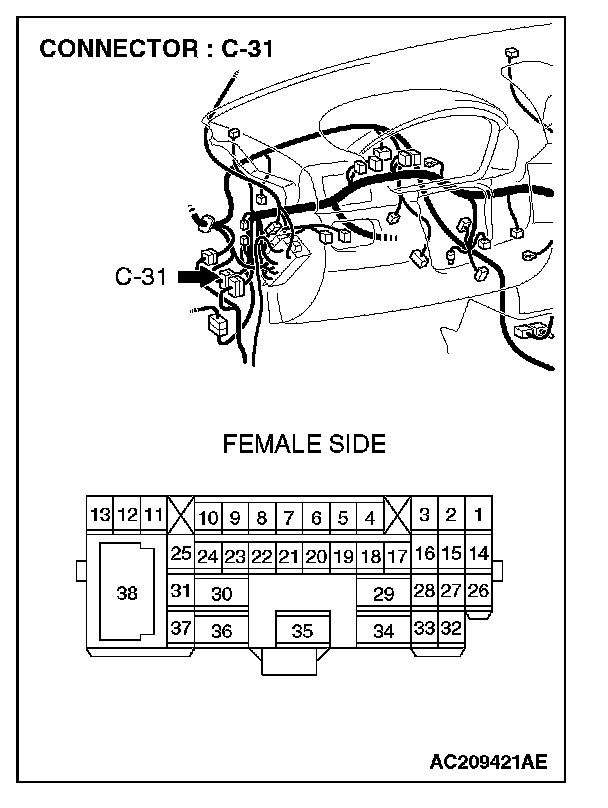
1. Disconnect intermediate connector C-31, and measure the resistance at its female side connector (instrument panel wiring harness side).
2. Turn the ignition switch to the "LOCK" (OFF) position.
CAUTION: Disconnect the negative battery terminal. For details refer to "Service Precautions".
3. Disconnect the negative battery terminal.
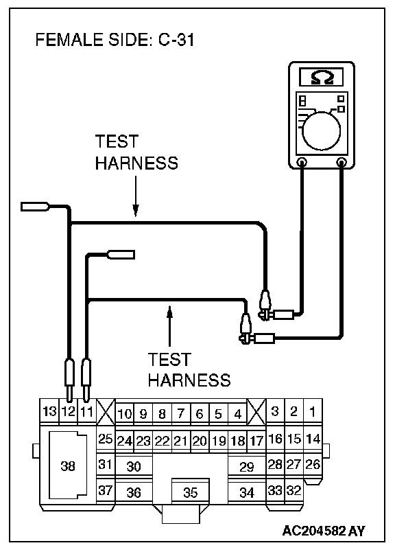
4. Measure the resistance between intermediate connector C-31 terminals 11 and 12.
OK: 120 ± 20 Ohms
Q: Does the resistance measure 120 ± 20 Ohms?
YES:
NO:
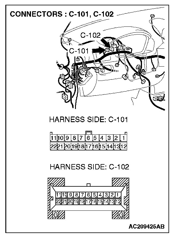
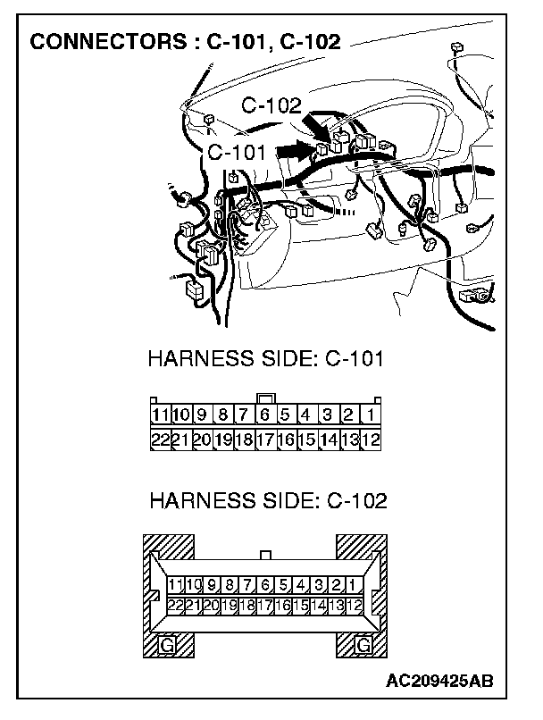
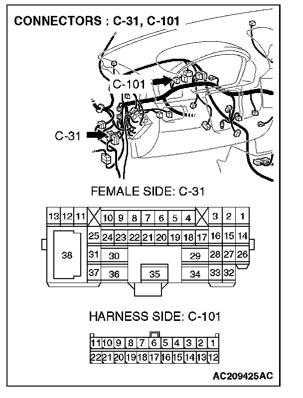
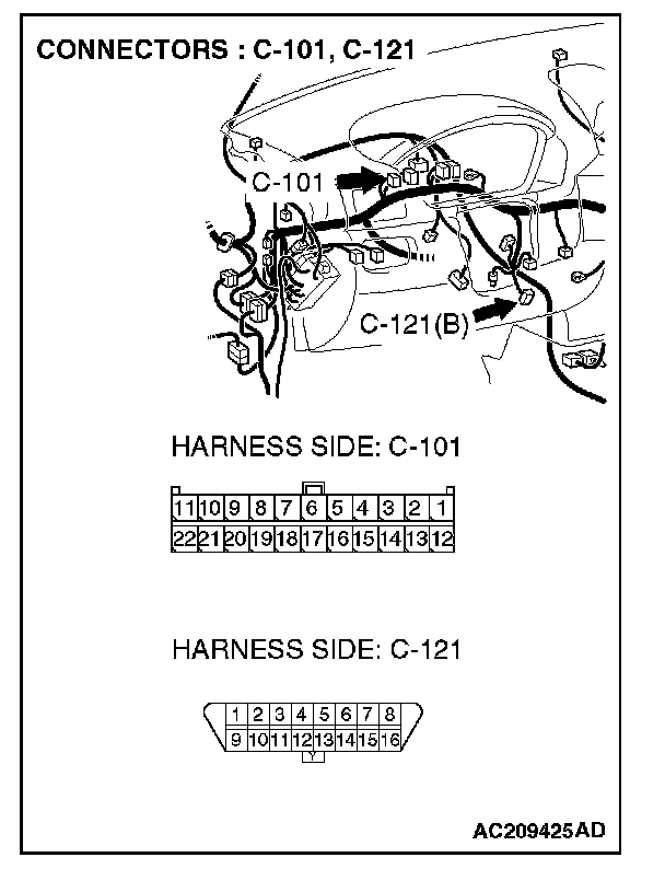
STEP 3. Check joint connector 4. C-101 and combination meter connector C-102 for loose, corroded or damaged terminals, or terminals pushed back in the connector.
CAUTION: The strand end of the twist wire should be within 10 cm from the connector. For details refer to "Service Precautions".
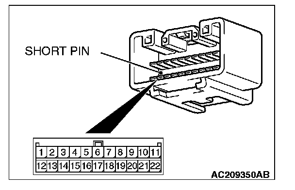
Check the joint connector at the wiring harness side for loose, corroded or damaged terminals, or terminals pushed back in the connector, and also check the short pin behind the connector for corrosion, deformation and delamination.
Q: Are joint connector 4. C-101 and combination meter connector C-102 in good condition?
YES: Go to Step 4.
NO: Repair the damaged parts. Replace the joint connector as necessary. Then go to Step 2.
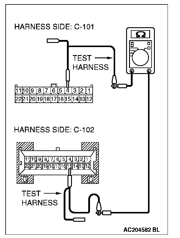
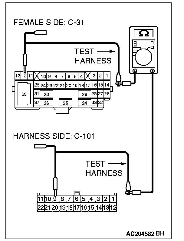
STEP 4. Check the CAN bus lines (communication line including the combination meter) between joint connector 4. and the combination meter. Measure the resistance at joint connector 4. C-101.
CAUTION: A digital multimeter should be used. For details refer to "Service Precautions".
CAUTION: The test wiring harness should be used. For details refer to "Service Precautions".
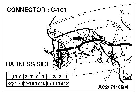
1. Disconnect joint connector 4. C-101, and measure the resistance at the wiring harness side of joint connector 4. C-101.
2. Turn the ignition switch to the "LOCK" (OFF) position.
CAUTION: Disconnect the negative battery terminal. For details refer to "Service Precautions".
3. Disconnect the negative battery terminal.
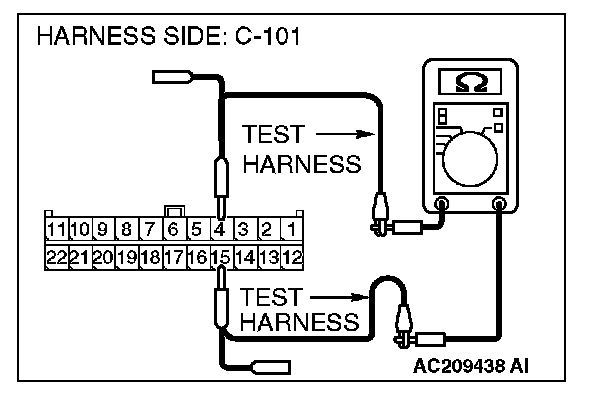
4. Measure the resistance between joint connector 4. terminals 4 and 15.
OK: 120 ± 20 Ohms
Q: Does the resistance measure 120 ± 20 Ohms?
YES:
NO:
STEP 5. Check the CAN bus lines (communication line only) between joint connector 4. and the combination meter. Measure the resistance at joint connector 4. C-101 and combination meter connector C-102.
CAUTION: A digital multimeter should be used. For details refer to "Service Precautions".
CAUTION: The test wiring harness should be used. For details refer to "Service Precautions".
1. Disconnect joint connector 4. C-101 and combination meter connector C-102, and measure the resistance between each wiring harness side connector.
2. Turn the ignition switch to the "LOCK" (OFF) position.
CAUTION: Disconnect the negative battery terminal. For details refer to "Service Precautions".
3. Disconnect the negative battery terminal.
4. Measure the resistance between joint connector 4. terminal 4 and combination meter connector terminal 15.
OK: 2 Ohms or less
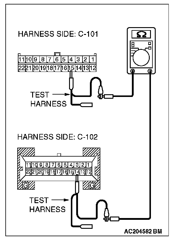
5. Measure the resistance between joint connector 4. terminal 15 and combination meter connector terminal 14.
OK: 2 Ohms or less
CAUTION: Strictly observe the specified wiring harness repair procedure. For details refer to "Precautions On How To Repair The CAN Bus Lines".
Q: Do all the resistances measure 2 Ohms or less?
YES:
NO:
STEP 6. Check the terminator resistor inside the combination meter. Measure the resistance at combination meter connector C-102.
CAUTION: A digital multimeter should be used. For details refer to "Service Precautions".
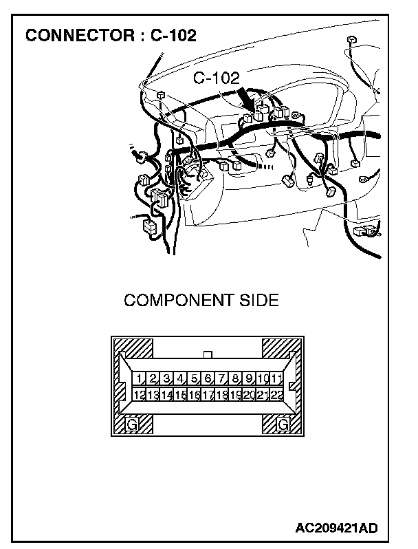
1. Disconnect combination meter C-102, and measure the resistance at the equipment side of combination meter connector C-102.
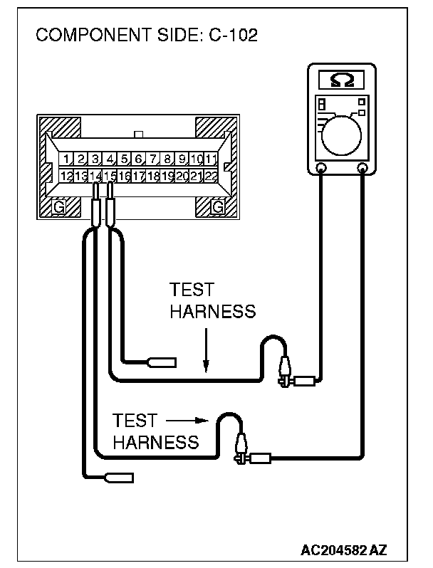
2. Measure the resistance between combination meter connector terminals 14 and 15.
OK: 120 ± 20 Ohms
Q: Does the resistance measure 120 ± 20 Ohms?
YES:
NO:
STEP 7. Check the CAN bus lines (communication line only) between intermediate connector C-31 and joint connector (4). Measure the resistance at intermediate connector C-31 and joint connector 4. C-101.
CAUTION: A digital multimeter should be used. For details refer to "Service Precautions".
CAUTION: The test wiring harness should be used. For details refer to "Service Precautions".
1. Disconnect joint connector 4. C-101 and intermediate connector C-31, and measure the resistance between the wiring harness side connector of joint connector 4. C-101 and the female side connector of intermediate connector C-31 (instrument panel wiring harness side).
2. Turn the ignition switch to the "LOCK" (OFF) position.
CAUTION: Disconnect the negative battery terminal. For details refer to "Service Precautions".
3. Disconnect the negative battery terminal.
4. Measure the resistance between joint connector 4. terminal 9 and intermediate connector C-31 terminal 12.
OK: 2 Ohms or less
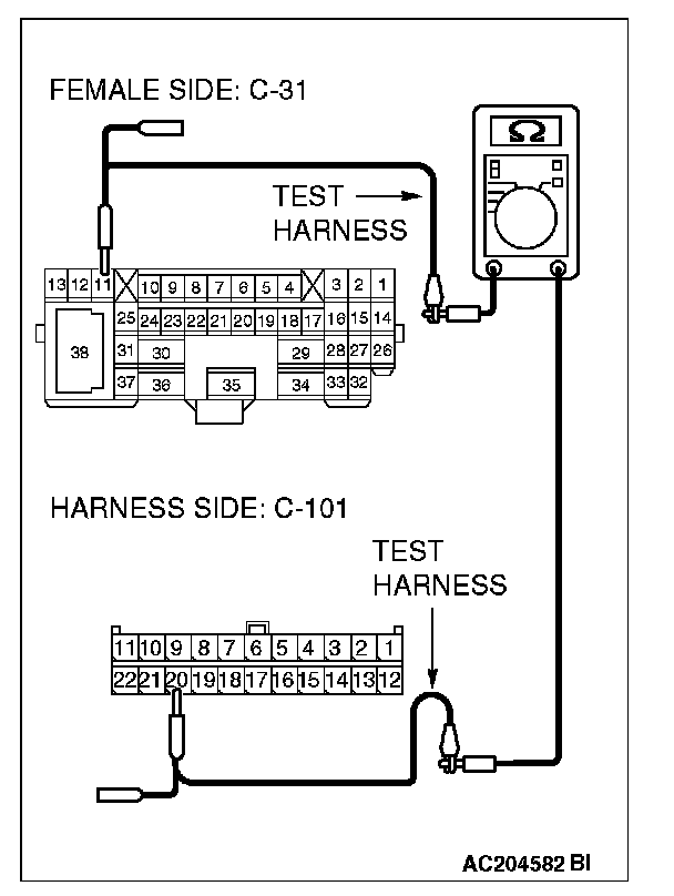
5. Measure the resistance between joint connector 4. terminal 20 and intermediate connector C-31 terminal 11.
OK: 2 Ohms or less
CAUTION: Strictly observe the specified wiring harness repair procedure. For details refer to "Precautions On How To Repair The CAN Bus Lines".
Q: Do all the resistances measure 2 Ohms or less?
YES:
NO:
STEP 8. Check the front wiring harness side CAN bus lines (communication line including the powertrain control module). Measure the resistance at intermediate connector C-31.
CAUTION: A digital multimeter should be used. For details refer to "Service Precautions".
CAUTION: The test wiring harness should be used. For details refer to "Service Precautions".
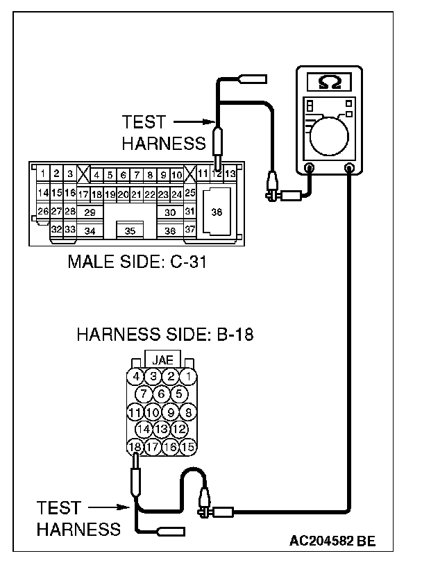
1. Disconnect intermediate connector C-31, and measure the resistance at the male side (at front wiring harness side).
2. Turn the ignition switch to the "LOCK" (OFF) position.
CAUTION: Disconnect the negative battery terminal. For details refer to "Service Precautions".
3. Disconnect the negative battery terminal.
4. Measure the resistance between intermediate connector C-31 terminals 11 and 12.
OK: 120 ± 20 Ohms
Q: Does the resistance measure 120 ± 20 Ohms?
YES:
NO:
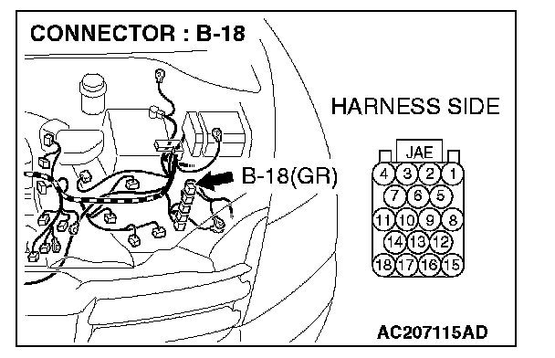
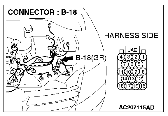
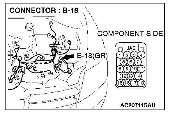
STEP 9. Check powertrain control module connector B-18 for loose, corroded or damaged terminals, or terminals pushed back in the connector.
CAUTION: The strand end of the twist wire should be within 10 cm from the connector. For details refer to "Service Precautions".
Q: Is powertrain control module connector B-18 in good condition?
YES: Go to Step 10.
NO: Repair the damaged parts, and then go to Step 8.
STEP 10. Check the CAN bus lines (communication line only) between intermediate connector C-31 and the powertrain control module. Measure the resistance at intermediate connector C-31 and powertrain control module connector C-18.
CAUTION: A digital multimeter should be used. For details refer to "Service Precautions".
CAUTION: The test wiring harness should be used. For details refer to "Service Precautions".
1. Disconnect intermediate connector C-31 and powertrain control module connector B-18, and measure the resistance between the wiring harness side connector of powertrain control module connector B-18 and the male side connector of intermediate connector C-31 (at front wiring harness side).
2. Turn the ignition switch to the "LOCK" (OFF) position.
CAUTION: Disconnect the negative battery terminal. For details refer to "Service Precautions".
3. Disconnect the negative battery terminal.
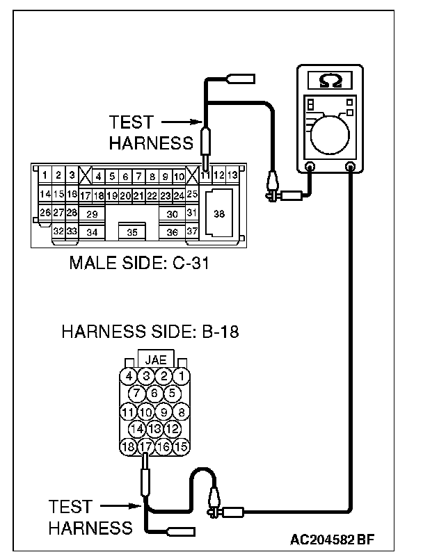
4. Measure the resistance between intermediate connector C-31 terminal 11 and powertrain control module connector terminal 17.
OK: 2 Ohms or less
5. Measure the resistance between intermediate connector C-31 terminal 12 and powertrain control module connector terminal 18.
OK: 2 Ohms or less
CAUTION: Strictly observe the specified wiring harness repair procedure. For details refer to "Precautions On How To Repair The CAN Bus Lines".
Q: Do all the resistances measure 2 Ohms or less?
YES:
NO:
STEP 11. Check the terminator resistor inside the powertrain control module. Measure the resistance at powertrain control module connector B-18.
CAUTION: A digital multimeter should be used. For details refer to "Service Precautions".
1. Disconnect powertrain control module connector B-18, and measure the resistance at the equipment side of powertrain control module connector B-18.
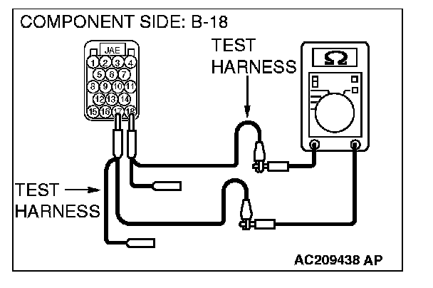
2. Measure the resistance between powertrain control module connector terminals 17 and 18.
OK: 120 ± 20 Ohms
Q: Does the resistance measure 120 ± 20 Ohms?
YES:
NO:
STEP 12. Check the CAN bus lines (communication line only) between joint connector 4. and the data link connector. Measure the resistance at joint connector 4. C-101 and data link connector C-121.
CAUTION: A digital multimeter should be used. For details refer to "Service Precautions".
CAUTION: The test wiring harness should be used. For details refer to "Service Precautions".
1. Disconnect joint connector (4), and measure the resistance between the wiring harness side connector of joint connector 4. and wiring harness side connector of data link connector C-121.
2. Turn the ignition switch to the "LOCK" (OFF) position.
CAUTION: Disconnect the negative battery terminal. For details refer to "Service Precautions".
3. Disconnect the negative battery terminal.
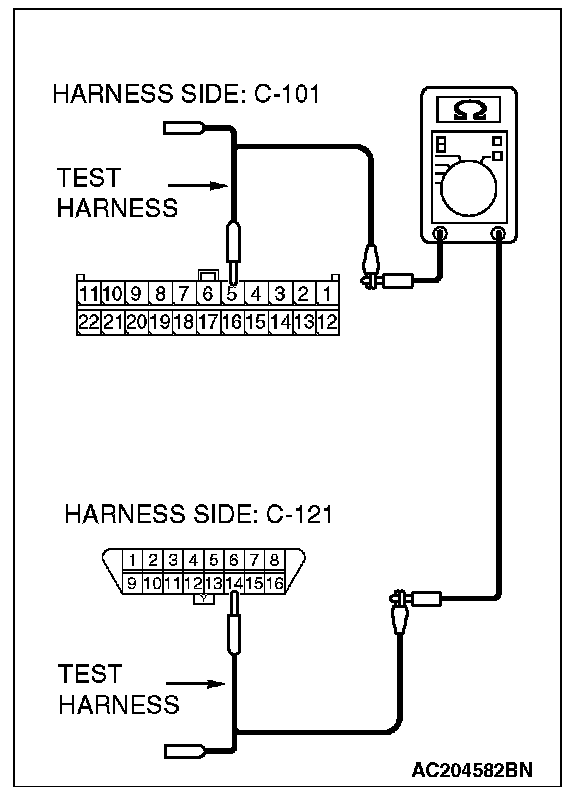
4. Measure the resistance between joint connector 4. terminal 5 and data link connector terminal 14.
OK: 2 Ohms or less
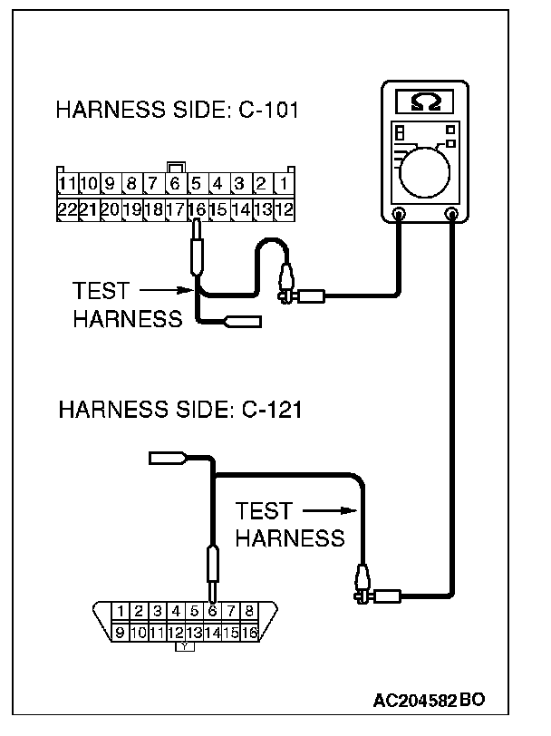
5. Measure the resistance between joint connector 4. terminal 16 and data link connector terminal 6.
OK: 2 Ohms or less
CAUTION: Strictly observe the specified wiring harness repair procedure. For details refer to "Precautions On How To Repair The CAN Bus Lines".
Q: Do all the resistances measure 2 Ohms or less?
YES:
YES: