Diagnostic Item 19
DIAGNOSTIC ITEM 19: Diagnose CAN bus lines thoroughlyPart 1:
Part 2:
TROUBLE JUDGMENT
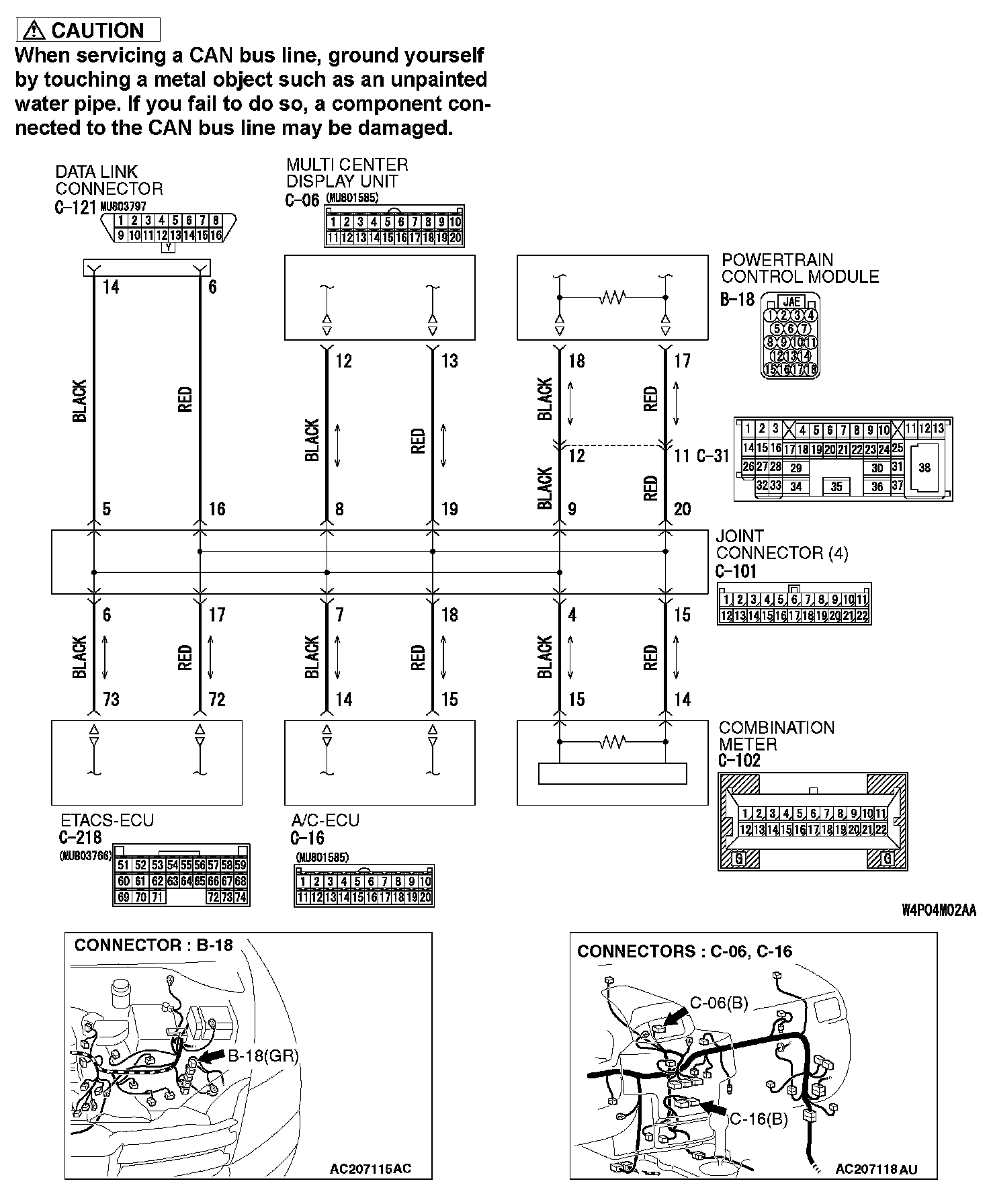
If the MUT-III cannot received signals from ECUs, CAN bus line connector(s) are broken or an open circuit has occurred.
COMMENTS ON TROUBLE SYMPTOM
The wiring harness wire or connectors may have loose, corroded, or damage terminals, or terminals pushed back in the connector, or an ECU may be defective.
TROUBLESHOOTING HINTS
- The wiring harness or connectors may have loose, corroded, or damage terminals, or terminals pushed back in the connector
- The ETACS-ECU may be defective
- The combination meter may be defective
- The A/C-ECU may be defective
- The multi-center display unit (middle-grade type) may be defective
- The powertrain control module may be defective
DIAGNOSIS
Required Special Tools:
- MB991223: Harness Set
- MB991958: Scan Tool (MUT-III Sub Assembly)
- MB991824: V.C.I.
- MB991827: USB Cable
- MB991910: Main Harness A
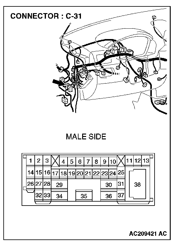
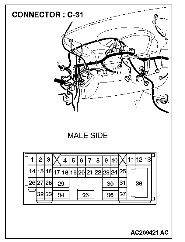
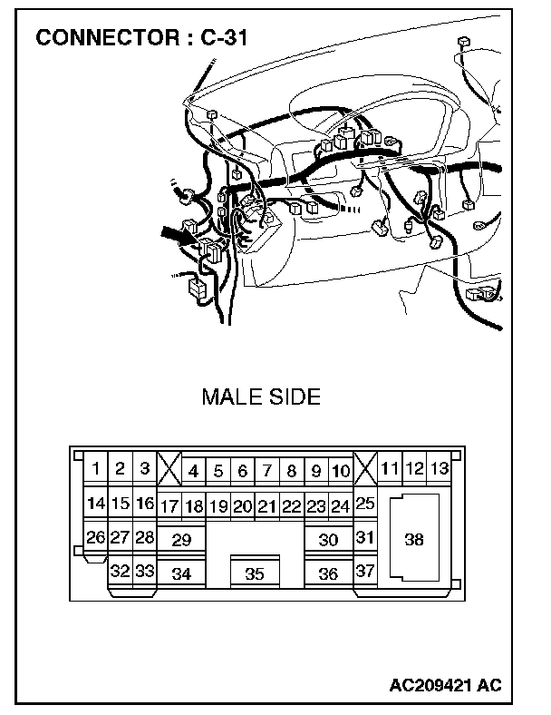
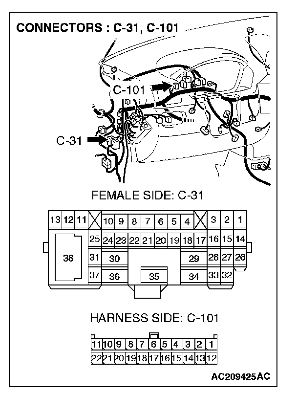
STEP 1. Check intermediate connector C-31 for loose, corroded or damaged terminals, or terminals pushed back in the connector.
CAUTION: The strand end of the twist wire should be within 10 cm from the connector. For details refer to "Service Precautions".
Q: Is intermediate connector C-31 in good condition?
YES: Go to Step 2.
NO: Repair the damaged parts.
STEP 2. Using scan tool MB991958, diagnose the CAN bus line (Disconnect intermediate connector C-31, and then determine that a failure is present at either the front wiring harness side or the instrument panel wiring harness side).
1. Disconnect intermediate connector C-31.
CAUTION: To prevent damage to scan tool MB991958, always turn the ignition switch to the "LOCK" (OFF) position before connecting or disconnecting scan tool MB991958.
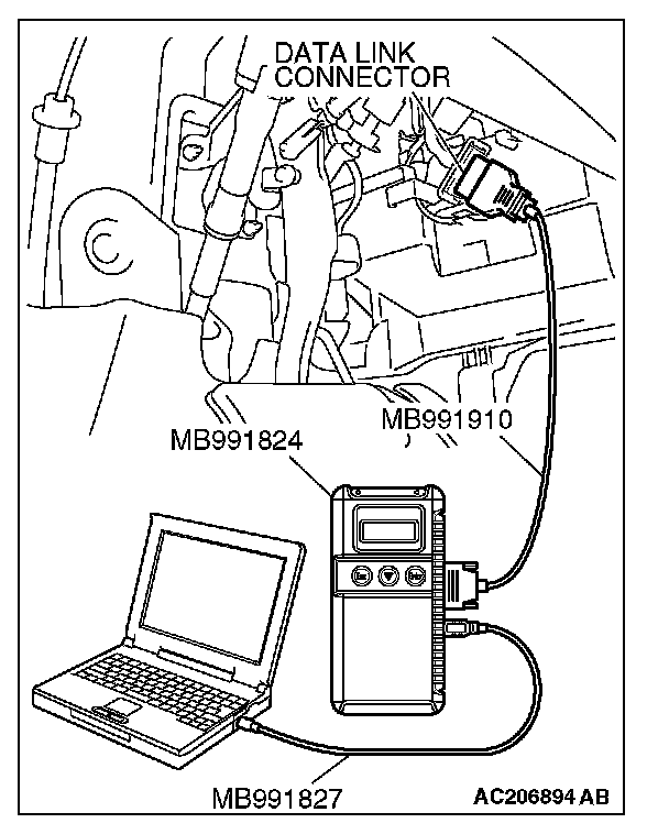
2. Connect scan tool MB991958 to the data link connector.
3. Turn the ignition switch to the "ON" position.
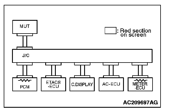
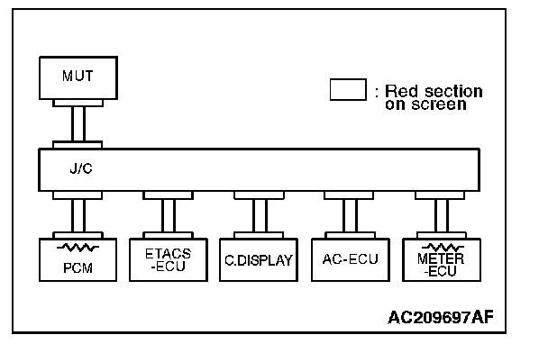
4. Diagnose CAN bus lines, and check if the MUT-III screen is as shown in the illustration.
5. Turn the ignition switch to the "LOCK" (OFF) position. 6. Connect intermediate connector C-31.
Q: Does the MUT-III screen correspond to the illustration?
YES:
NO:
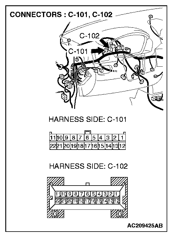
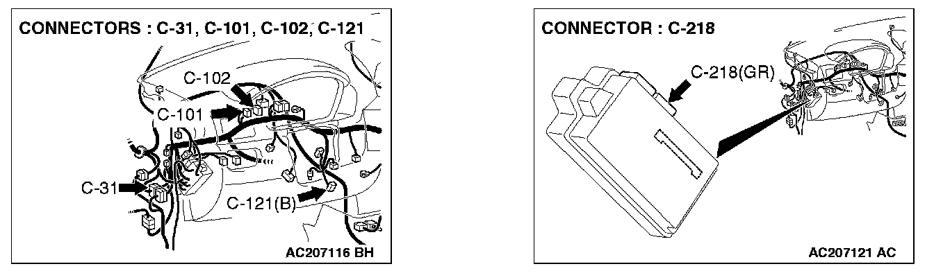
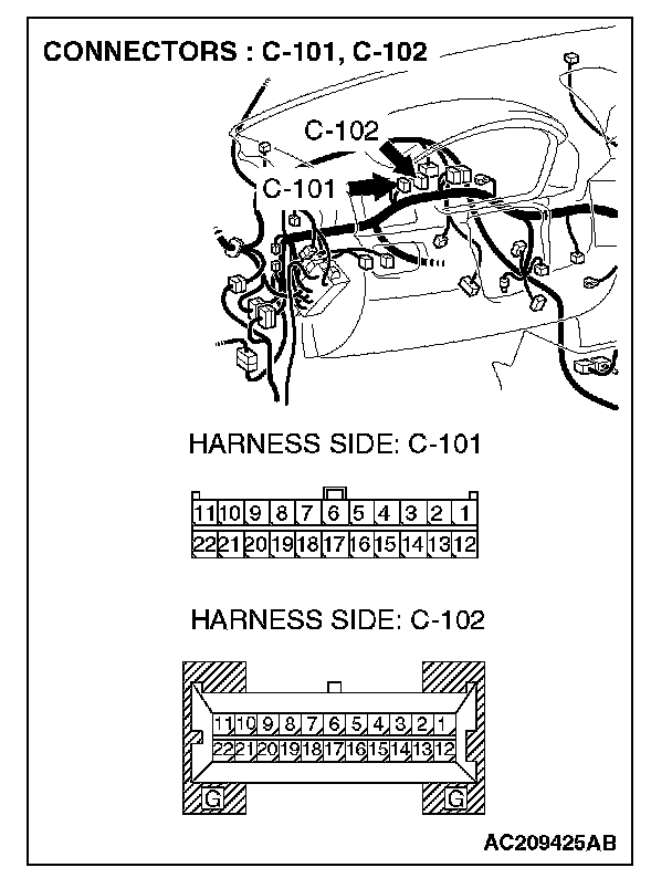
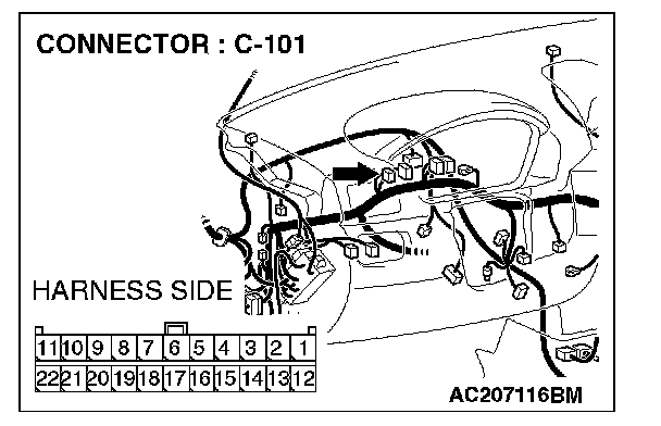
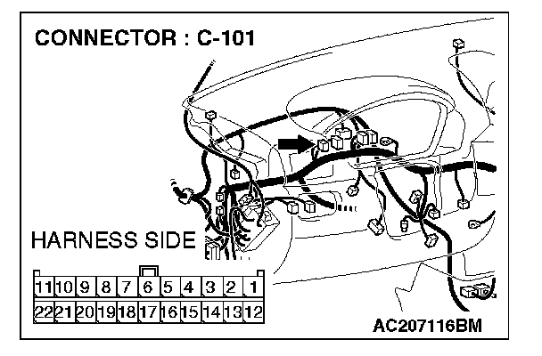
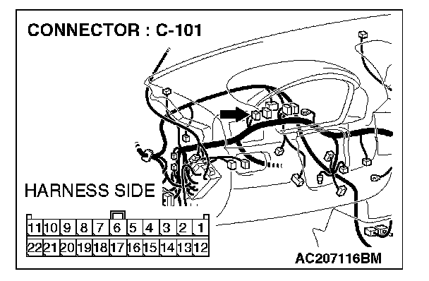
STEP 3. Check joint connector 4. C-101 and combination meter connector C-102 for loose, corroded or damaged terminals, or terminals pushed back in the connector.
CAUTION: The strand end of the twist wire should be within 10 cm from the connector. For details refer to "Service Precautions".
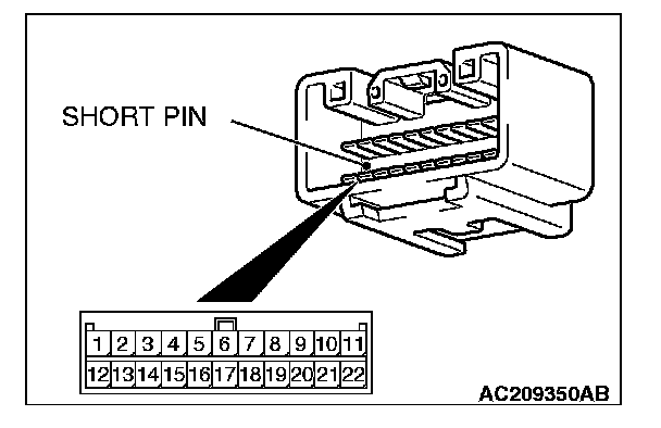
Check the joint connector at the wiring harness side for loose, corroded or damaged terminals, or terminals pushed back in the connector, and also check the short pin behind the connector for corrosion, deformation and delamination.
Q: Is joint connector 4. C-101 in good condition?
YES: Go to Step 4.
NO: Repair the damaged parts. Replace the joint connector as necessary.
STEP 4. Using scan tool MB991958, diagnose the CAN bus line (Disconnect combination meter connector C-102, and check the combination meter system).
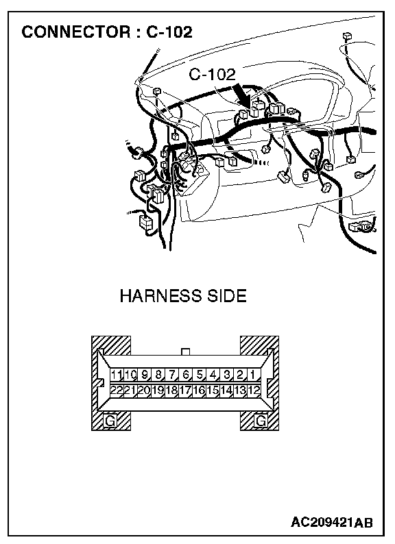
1. Disconnect combination meter connector C-102.
2. Turn the ignition switch to the "ON" position.
3. Diagnose CAN bus lines, and check if the MUT-III screen is as shown in the illustration.
4. Turn the ignition switch to the "LOCK" (OFF) position.
5. Disconnect combination meter connector C-102.
Q: Does the MUT-III screen correspond to the illustration?
YES:
NO:
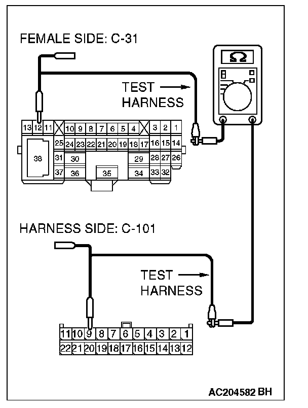
STEP 5. Check the CAN bus lines between joint connector 4. and the combination meter. Measure the resistance between joint connector 4. C-101 and combination meter connector C-102.
CAUTION: A digital multimeter should be used. For details refer to "Service Precautions".
CAUTION: The test wiring harness should be used. For details refer to "Service Precautions".
1. Disconnect joint connector 4. C-101 and combination meter connector C-102, and measure the resistance between each wiring harness side connector.
2. Turn the ignition switch to the "LOCK" (OFF) position.
CAUTION: Disconnect the negative battery terminal. For details refer to "Service Precautions".
3. Disconnect the negative battery terminal.
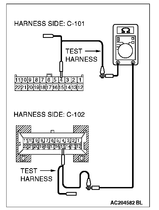
4. Measure the resistance between joint connector 4. terminal 4 and combination meter connector terminal 15.
OK: 2 Ohms or less
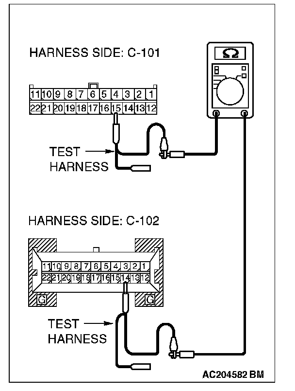
5. Measure the resistance between joint connector 4. terminal 15 and combination meter connector terminal 14.
OK: 2 Ohms or less
CAUTION: Strictly observe the specified wiring harness repair procedure. For details refer to "Precautions On How To Repair The CAN Bus Lines".
Q: Do all the resistances measure 2 Ohms or less?
YES:
NO:
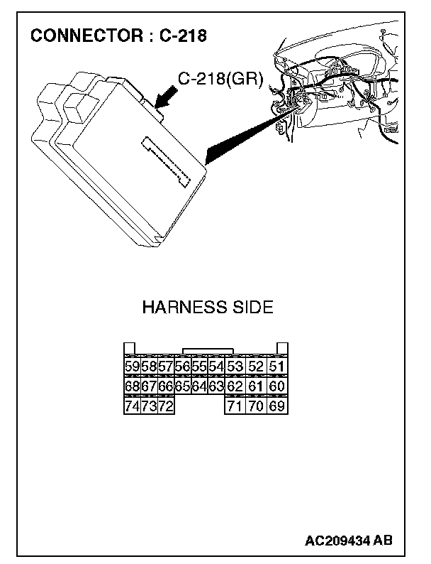
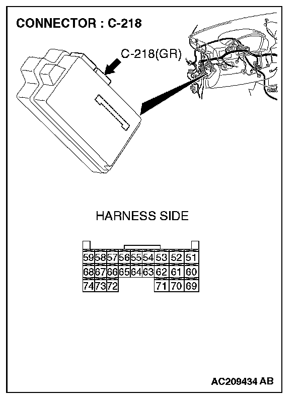
STEP 6. Check ETACS-ECU connector C-218 for loose, corroded or damaged terminals, or terminals pushed back in the connector.
CAUTION: The strand end of the twist wire should be within 10 cm from the connector. For details refer to "Service Precautions".
Q: Is ETACS-ECU connector C-218 in good condition?
YES: Go to Step 7.
NO: Repair the damaged parts.
STEP 7. Using scan tool MB991958, diagnose the CAN bus line (Disconnect ETACS-ECU connector C-218, and check the ETACS-ECU system).
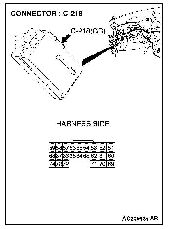
1. Disconnect ETACS-ECU connector C-218.
2. Turn the ignition switch to the "ON" position.
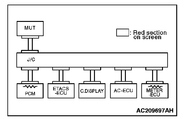
3. Diagnose CAN bus lines, and check if the MUT-III screen is as shown in the illustration.
4. Turn the ignition switch to the "LOCK" (OFF) position.
5. Connect ETACS-ECU connector C-218.
Q: Does the MUT-III screen correspond to the illustration?
YES:
NO:
STEP 8. Check the CAN bus lines between joint connector 4. and the ETACS-ECU. Measure the resistance between joint connector 4. C-101 and ETACS-ECU connector C-218.
CAUTION: A digital multimeter should be used. For details refer to "Service Precautions".
CAUTION: The test wiring harness should be used. For details refer to "Service Precautions".
1. Disconnect joint connector 4. C-101 and ETACS-ECU connector C-218, and measure the resistances at the wiring harness sides of joint connector 4. C-101 and ETACS-ECU connector C-218.
2. Turn the ignition switch to the "LOCK" (OFF) position.
CAUTION: Disconnect the negative battery terminal. For details refer to "Service Precautions".
3. Disconnect the negative battery terminal.
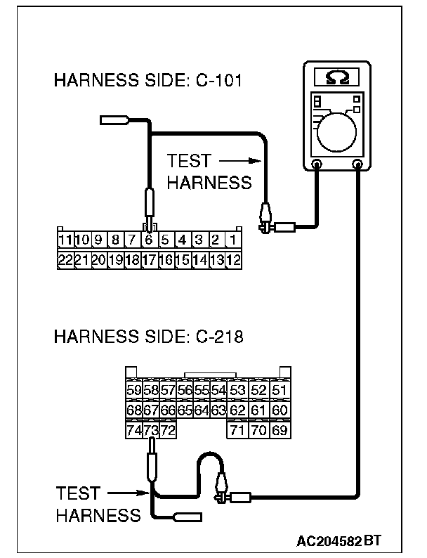
4. Measure the resistance between joint connector 4. terminal 6 and ETACS-ECU connector terminal 73.
OK: 2 Ohms or less
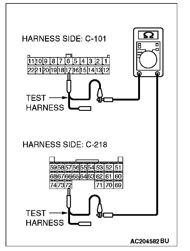
5. Measure the resistance between joint connector 4. terminal 17 and ETACS-ECU connector terminal 72.
OK: 2 Ohms or less
CAUTION: Strictly observe the specified wiring harness repair procedure. For details refer to "Precautions On How To Repair The CAN Bus Lines".
Q: Do all the resistances measure 2 Ohms or less?
YES:
NO:
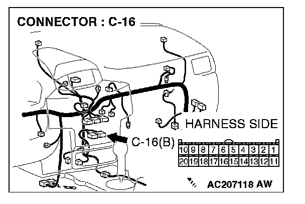
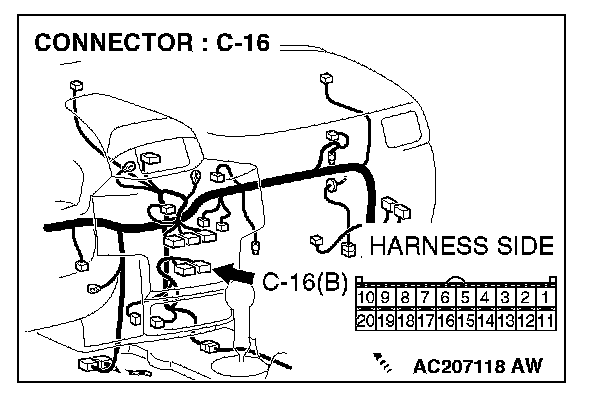
STEP 9. Check A/C-ECU connector C-16 for loose, corroded or damaged terminals, or terminals pushed back in the connector.
CAUTION: The strand end of the twist wire should be within 10 cm from the connector. For details refer to "Service Precautions".
Q: Is A/C-ECU connector C-16 in good condition?
YES: Go to Step 10.
NO: Repair the damaged parts.
STEP 10. Using scan tool MB991958, diagnose the CAN bus line (Disconnect A/C-ECU connector C-16, and check the A/C-ECU system).
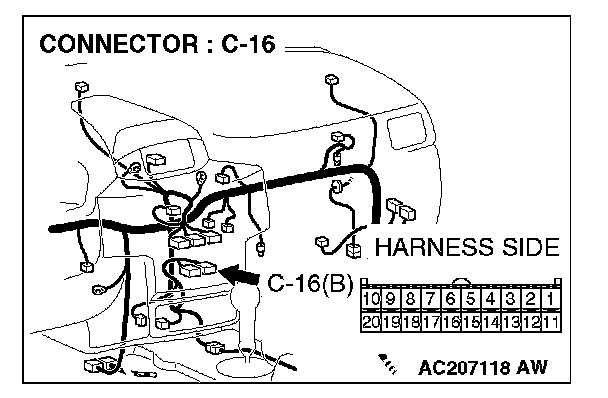
1. Disconnect A/C-ECU connector C-16.
2. Turn the ignition switch to the "ON" position.
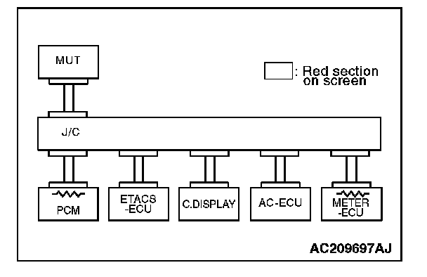
3. Diagnose CAN bus lines, and check if the MUT-III screen is as shown in the illustration.
4. Turn the ignition switch to the "LOCK" (OFF) position.
5. Connect A/C-ECU connector C-16.
Q: Does the MUT-III screen correspond to the illustration?
YES:
NO:
STEP 11. Check the CAN bus lines between joint connector 4. and the A/C-ECU. Measure the resistance between joint connector 4. C-101 and A/C-ECU connector C-16.
CAUTION: A digital multimeter should be used. For details refer to "Service Precautions".
CAUTION: The test wiring harness should be used. For details refer to "Service Precautions".
1. Disconnect joint connector 4. C-101 and A/C-ECU connector C-16, and measure the resistances at the wiring harness sides of joint connector 4. C-101 and A/C-ECU connector C-16.
2. Turn the ignition switch to the "LOCK" (OFF) position.
CAUTION: Disconnect the negative battery terminal. For details refer to "Service Precautions".
3. Disconnect the negative battery terminal.
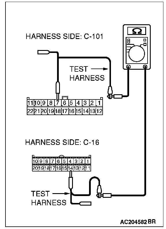
4. Measure the resistance between joint connector 4. terminal 7 and A/C-ECU connector terminal 14.
OK: 2 Ohms or less
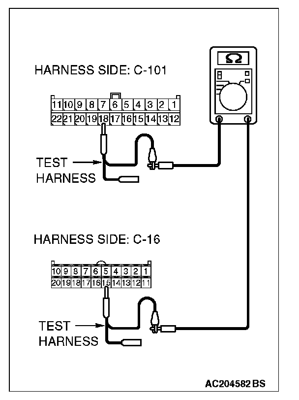
5. Measure the resistance between joint connector 4. terminal 18 and A/C-ECU connector terminal 15.
OK: 2 Ohms or less
CAUTION: Strictly observe the specified wiring harness repair procedure. For details refer to "Precautions On How To Repair The CAN Bus Lines".
Q: Do all the resistances measure 2 Ohms or less?
YES:
NO:
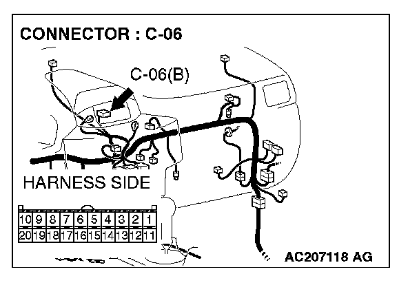
STEP 12. Check multi-center display unit (middle-grade type) connector C-06 for loose, corroded or damaged terminals, or terminals pushed back in the connector.
CAUTION: The strand end of the twist wire should be within 10 cm from the connector. For details refer to "Service Precautions".
Q: Is multi-center display unit (middle-grade type) connector C-06 in good condition?
YES: Go to Step 13.
NO: Repair the damaged parts.
STEP 13. Using scan tool MB991958, diagnose the CAN bus line (Disconnect middle-grade multi-center display connector C-06, and check the middle-grade multi-center display system).
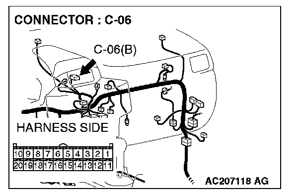
1. Disconnect multi-center display unit (middle-grade type) connector C-06.
2. Turn the ignition switch to the "ON" position.
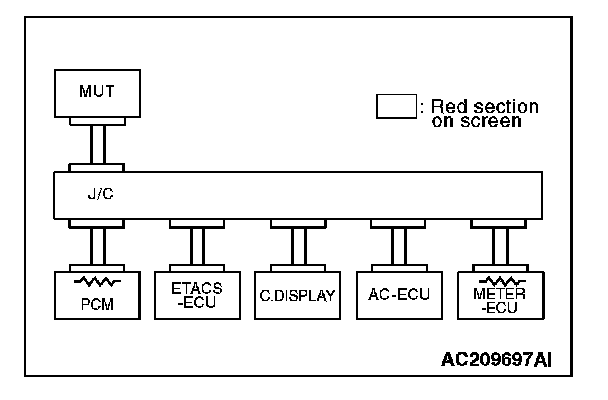
3. Diagnose CAN bus lines, and check if the MUT-III screen is as shown in the illustration.
4. Turn the ignition switch to the "LOCK" (OFF) position.
5. Connect the middle-grade multi-center display connector C-06.
Q: Does the MUT-III screen correspond to the illustration?
YES:
NO:
STEP 14. Check the CAN bus lines between joint connector 4. and the middle-grade multi-center display. Measure the resistance between joint connector 4. C-101 and middle-grade multi-center display connector C-06.
CAUTION: A digital multimeter should be used. For details refer to "Service Precautions".
CAUTION: The test wiring harness should be used. For details refer to "Service Precautions".
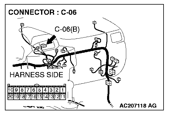
1. Disconnect joint connector 4. C-101 and multi-center display unit (middle-grade type) connector C-06, and measure the resistance at the wiring harness sides of joint connector 4. C-101 and multi-center display unit (middle-grade type) connector C-06.
2. Turn the ignition switch to the "LOCK" (OFF) position.
CAUTION: Disconnect the negative battery terminal. For details refer to "Service Precautions".
3. Disconnect the negative battery terminal.
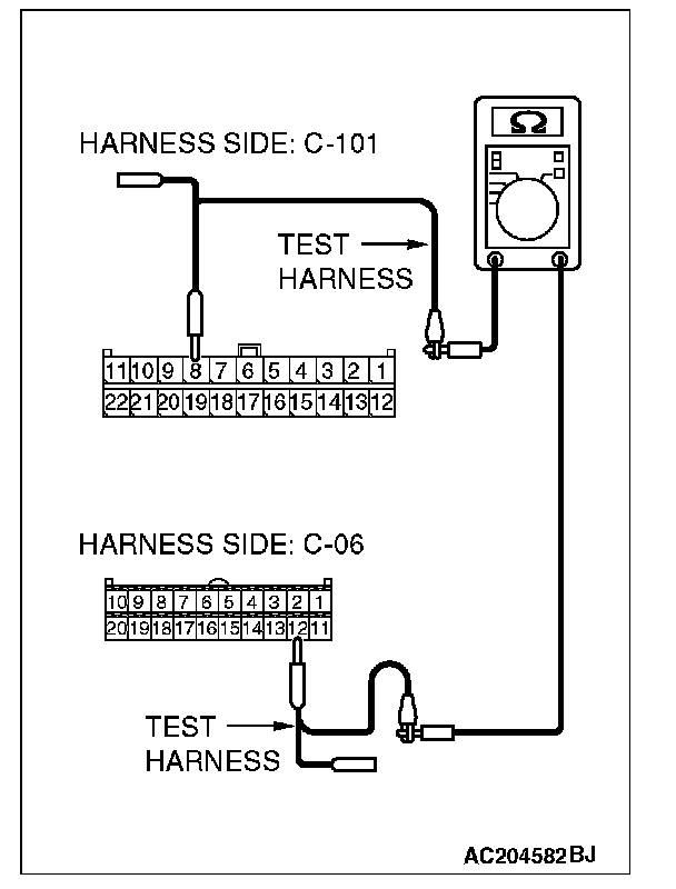
4. Measure the resistance between joint connector 4. terminal 8 and middle-grade multi-center display connector terminal 12.
OK: 2 Ohms or less
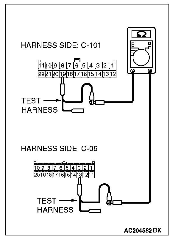
5. Measure the resistance between joint connector 4. terminal 19 and middle-grade multi-center display connector terminal 13.
OK: 2 Ohms or less
CAUTION: Strictly observe the specified wiring harness repair procedure. For details refer to "Precautions On How To Repair The CAN Bus Lines".
Q: Do all the resistances measure 2 Ohms or less?
YES:
NO:
STEP 15. Check the CAN bus lines between joint connector 4. and the data link connector. Measure the resistance between joint connector 4. C-101 and data link connector C-121.
CAUTION: A digital multimeter should be used. For details refer to "Service Precautions".
CAUTION: The test wiring harness should be used. For details refer to "Service Precautions".
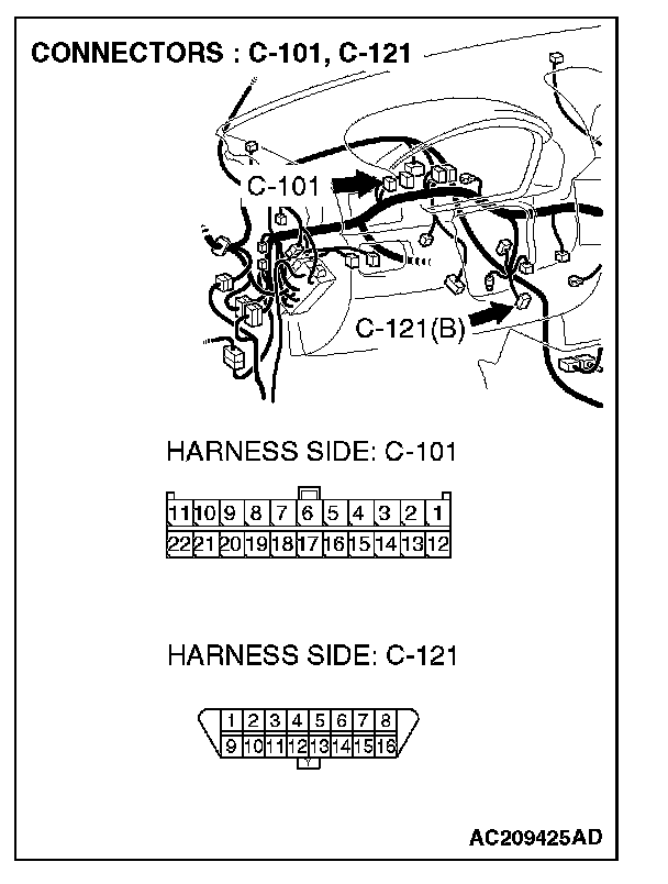
1. Disconnect joint connector 4. C-101, and measure the resistance between the wiring harness side connector of joint connector 4. C-101 and wiring harness side connector of data link connector C-121.
2. Turn the ignition switch to the "LOCK" (OFF) position.
CAUTION: Disconnect the negative battery terminal. For details refer to "Service Precautions".
3. Disconnect the negative battery terminal.
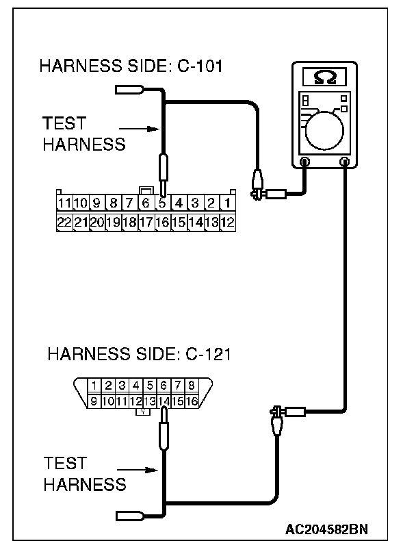
4. Measure the resistance between joint connector 4. terminal 5 and data link connector terminal 14.
OK: 2 Ohms or less
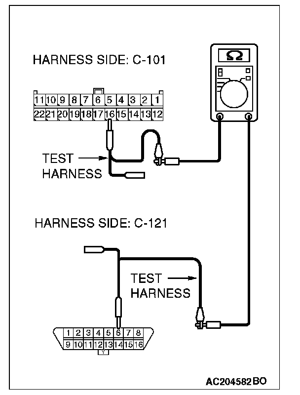
5. Measure the resistance between joint connector 4. terminal 16 and data link connector terminal 6.
OK: 2 Ohms or less
CAUTION: Strictly observe the specified wiring harness repair procedure. For details refer to "Precautions On How To Repair The CAN Bus Lines".
Q: Do all the resistances measure 2 Ohms or less?
YES:
NO:
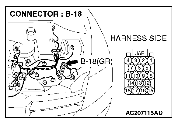
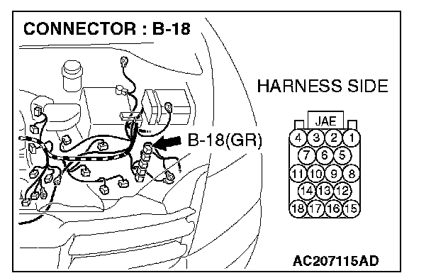
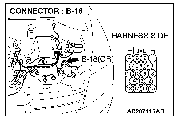
STEP 16. Check powertrain control module connector B-18 for loose, corroded or damaged terminals, or terminals pushed back in the connector.
CAUTION: The strand end of the twist wire should be within 10 cm from the connector. For details refer to "Service Precautions".
Q: Is powertrain control module connector B-18 in good condition?
YES: Go to Step 17.
NO: Repair the damaged parts.
STEP 17. Using scan tool MB991958, diagnose the CAN bus line (Disconnect powertrain control module connector B-18, and check the powertrain control module system).
1. Disconnect powertrain control module connector B-18.
2. Turn the ignition switch to the "ON" position.
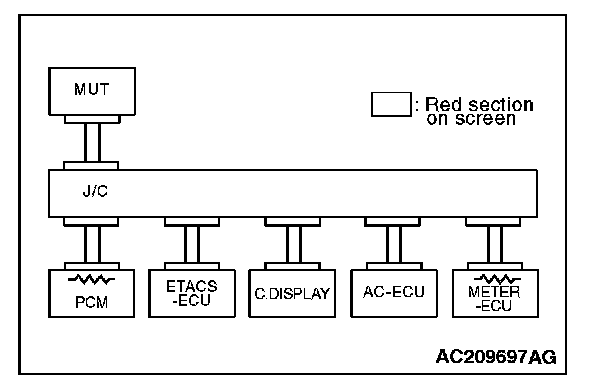
3. Diagnose CAN bus lines, and check if the MUT-III screen is as shown in the illustration.
4. Turn the ignition switch to the "LOCK" (OFF) position.
5. Connect powertrain control module connector B-18.
Q: Does the MUT-III screen correspond to the illustration?
YES:
NO:
STEP 18. Check the CAN bus lines between intermediate connector C-31 and the powertrain control module. Measure the resistance between intermediate connector C-31 and powertrain control module connector B-18.
CAUTION: A digital multimeter should be used. For details refer to "Service Precautions".
CAUTION: The test wiring harness should be used. For details refer to "Service Precautions".
1. Disconnect intermediate connector C-31 and powertrain control module connector B-18, and measure the resistance between the wiring harness side connector of powertrain control module connector B-18 and the male side connector of intermediate connector C-31 (at front wiring harness side).
2. Turn the ignition switch to the "LOCK" (OFF) position.
CAUTION: Disconnect the negative battery terminal. For details refer to "Service Precautions".
3. Disconnect the negative battery terminal.
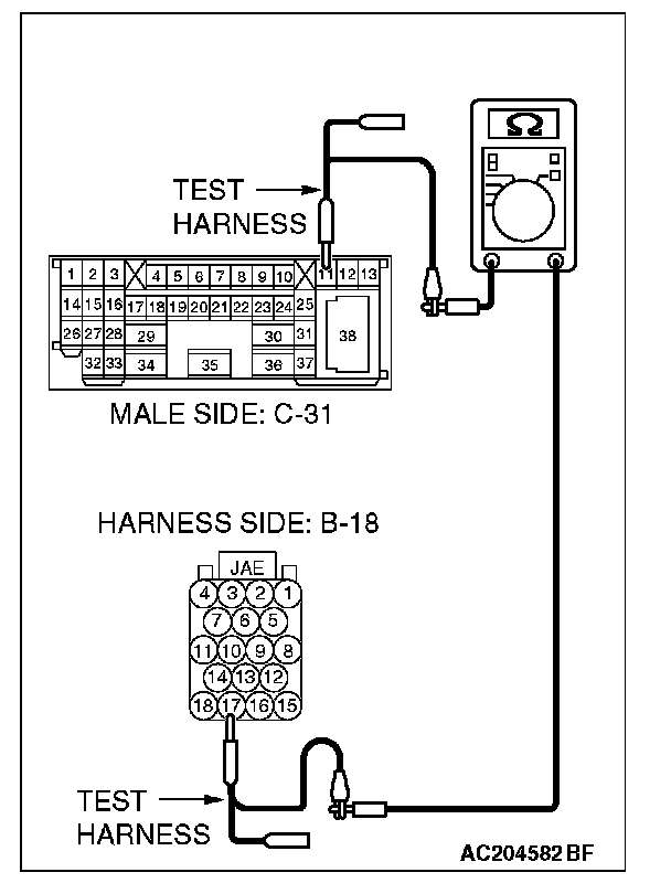
4. Measure the resistance between intermediate connector C-31 terminal 11 and powertrain control module connector terminal 17.
OK: 2 Ohms or less
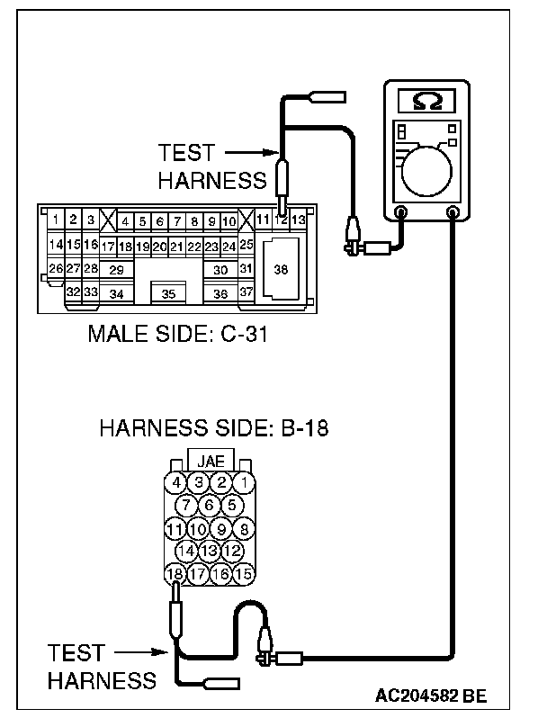
5. Measure the resistance between intermediate connector C-31 terminal 12 and powertrain control module connector terminal 18.
OK: 2 Ohms or less
CAUTION: Strictly observe the specified wiring harness repair procedure. For details refer to "Precautions On How To Repair The CAN Bus Lines".
Q: Do all the resistances measure 2 Ohms or less?
YES:
NO:
STEP 19. Check the CAN bus lines between intermediate connector C-31 and the joint connector (4). Measure the resistance between intermediate connector C-31 and joint connector 4. C-101.
CAUTION: A digital multimeter should be used. For details refer to "Service Precautions".
CAUTION: The test wiring harness should be used. For details refer to "Service Precautions".
1. Disconnect joint connector 4. C-101 and intermediate connector C-31, and measure the resistance between the wiring harness side connector of joint connector 4. C-101 and the female side connector of intermediate connector C-31 (instrument panel wiring harness side).
2. Turn the ignition switch to the "LOCK" (OFF) position.
CAUTION: Disconnect the negative battery terminal. For details refer to "Service Precautions".
3. Disconnect the negative battery terminal.
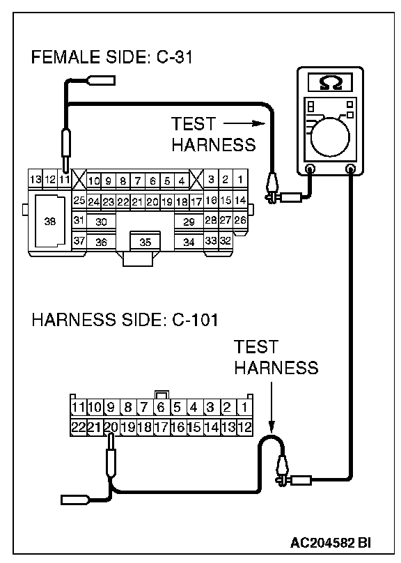
4. Measure the resistance between joint connector 4. terminal 20 and intermediate connector C-31 terminal 11.
OK: 2 Ohms or less
5. Measure the resistance between joint connector 4. terminal 9 and intermediate connector C-31 terminal 12.
OK: 2 Ohms or less
CAUTION: Strictly observe the specified wiring harness repair procedure. For details refer to "Precautions On How To Repair The CAN Bus Lines".
Q: Do all the resistances measure 2 Ohms or less?
YES:
NO: