Diagnostic Item 21
DIAGNOSTIC ITEM 21: Diagnose the lines between CAN main bus line and the powertrain control module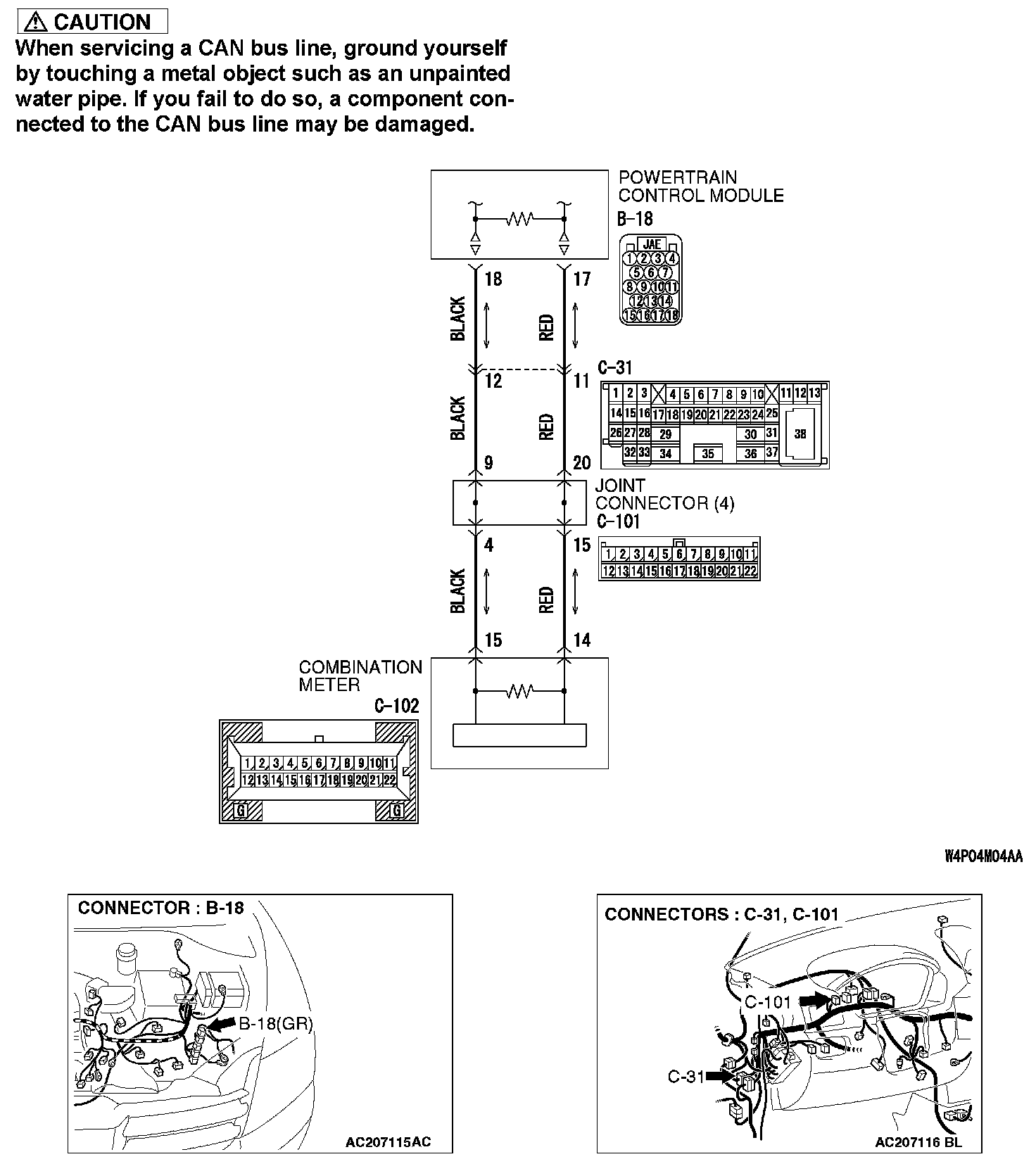
TROUBLE JUDGMENT
If the MUT-III cannot received signals from the powertrain control module, CAN bus line connector(s) are broken or an open circuit has occurred.
COMMENTS ON TROUBLE SYMPTOM
The wiring harness wire or connectors may have loose, corroded, or damage terminals, or terminals pushed back in the connector, or the powertrain control module may be defective.
TROUBLESHOOTING HINTS
- The wiring harness or connectors may have loose, corroded, or damage terminals, or terminals pushed back in the connector
- The powertrain control module may be defective
DIAGNOSIS
Required Special Tools:
- MB991223: Harness Set

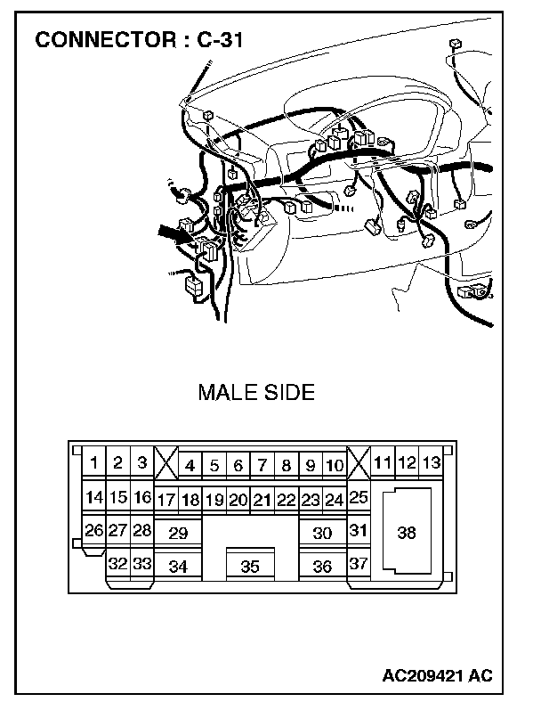
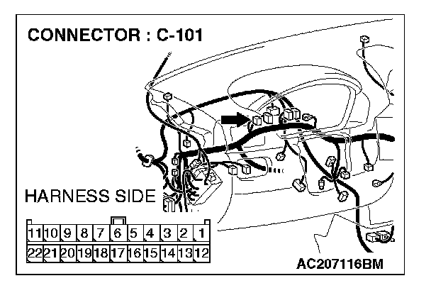
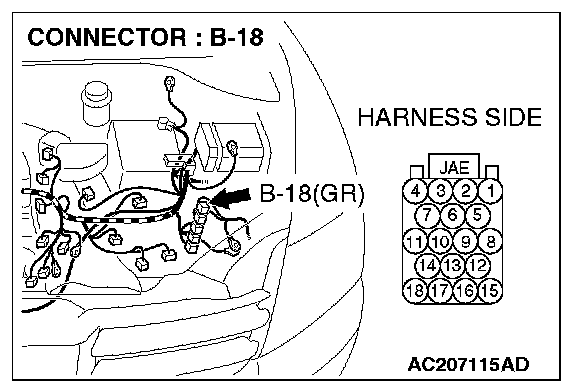
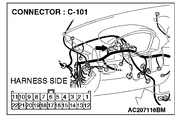
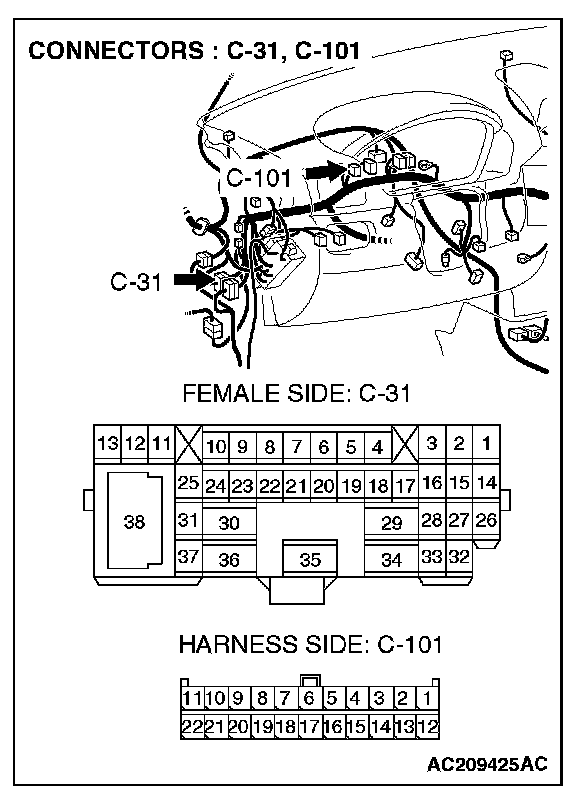
STEP 1. Check intermediate connector C-31, joint connector 4. C-101 and powertrain control module connector B-18 for loose, corroded or damaged terminals, or terminals pushed back in the connector.
CAUTION: The strand end of the twist wire should be within 10 cm from the connector. For details refer to "Service Precautions".
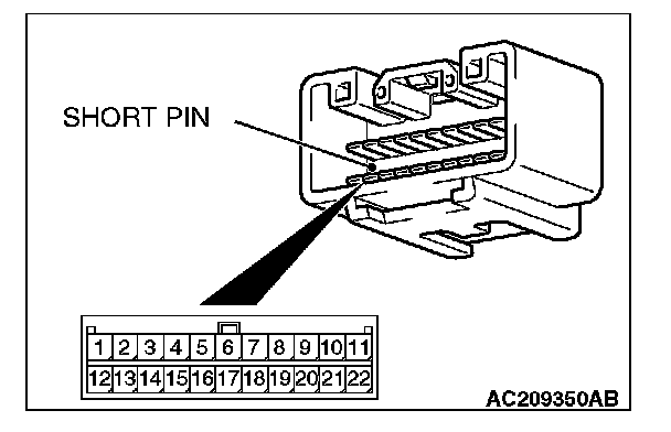
Check the joint connector at the wiring harness side for loose, corroded or damaged terminals, or terminals pushed back in the connector, and also check the short pin behind the connector for corrosion, deformation and delamination.
Q: Are intermediate connector C-31, joint connector 4. C-101 and powertrain control module connector B-18 in good condition?
YES: Go to Step 2.
NO: Repair the damaged parts. Replace the joint connector as necessary.
STEP 2. Check the CAN bus lines between intermediate connector C-31 and the powertrain control module. Measure the resistance between intermediate connector C-31 and powertrain control module connector B-18.
CAUTION: A digital multimeter should be used. For details refer to "Service Precautions".
CAUTION: The test wiring harness should be used. For details refer to "Service Precautions".
1. Disconnect intermediate connector C-31 and powertrain control module connector B-18, and measure the resistance between the wiring harness side connector of powertrain control module connector B-18 and the male side connector of intermediate connector C-31 (at front wiring harness side).
2. Turn the ignition switch to the "LOCK" (OFF) position.
CAUTION: Disconnect the negative battery terminal. For details refer to "Service Precautions".

3. Disconnect the negative battery terminal.
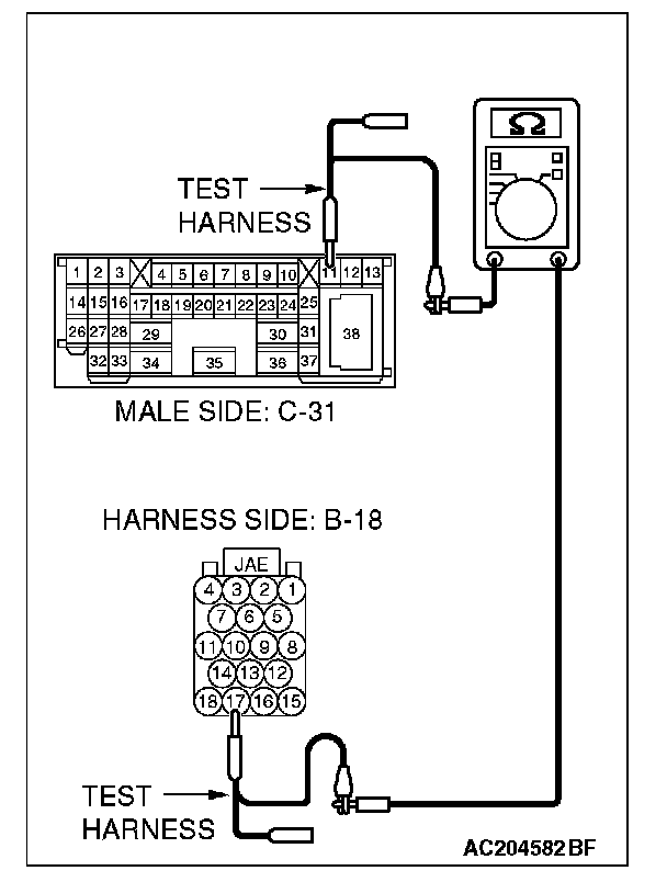
4. Measure the resistance between intermediate connector C-31 terminal 11 and powertrain control module connector terminal 17.
OK: 2 Ohms or less
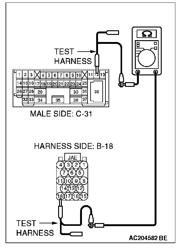
5. Measure the resistance between intermediate connector C-31 terminal 12 and powertrain control module connector terminal 18.
OK: 2 Ohms or less
CAUTION: Strictly observe the specified wiring harness repair procedure. For details refer to "Precautions On How To Repair The CAN Bus Lines".
Q: Do all the resistances measure 2 Ohms or less?
YES:
NO:
STEP 3. Check the CAN bus lines between intermediate connector C-31 and the joint connector (4). Measure the resistance between intermediate connector C-31 and joint connector 4. C-101.
CAUTION: A digital multimeter should be used. For details refer to "Service Precautions".
CAUTION: The test wiring harness should be used. For details refer to "Service Precautions".
1. Disconnect joint connector 4. C-101 and intermediate connector C-31, and measure the resistance between the wiring harness side connector of joint connector 4. C-101 and the female side connector of intermediate connector C-31 (instrument panel wiring harness side).
2. Turn the ignition switch to the "LOCK" (OFF) position.
CAUTION: Disconnect the negative battery terminal. For details refer to "Service Precautions".
3. Disconnect the negative battery terminal.
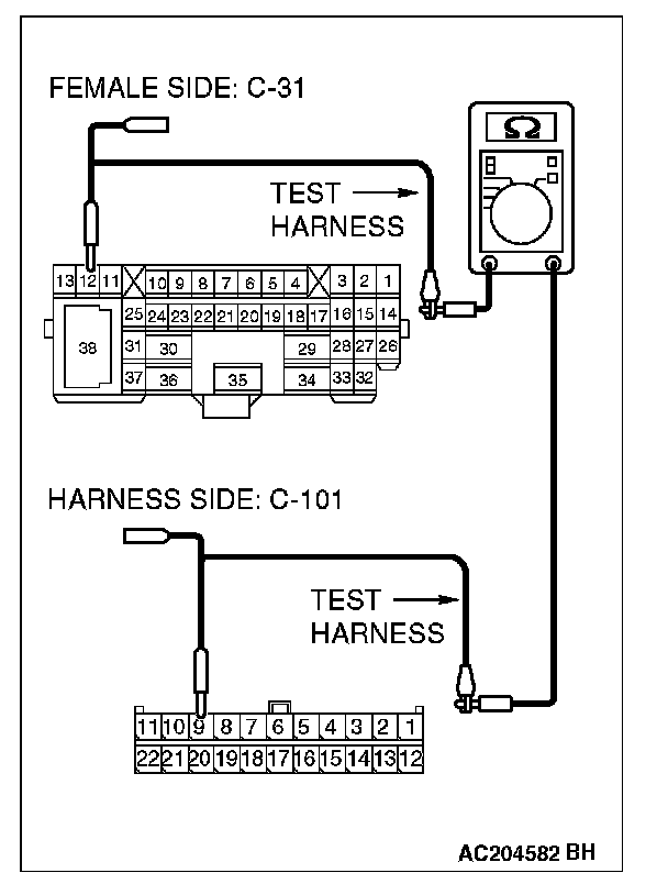
4. Measure the resistance between joint connector 4. terminal 9 and intermediate connector C-31 terminal 12.
OK: 2 Ohms or less
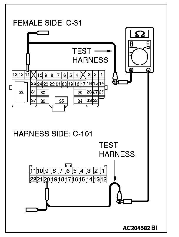
5. Measure the resistance between joint connector 4. terminal 20 and intermediate connector C-31 terminal 11.
OK: 2 Ohms or less
CAUTION: Strictly observe the specified wiring harness repair procedure. For details refer to "Precautions On How To Repair The CAN Bus Lines".
Q: Do all the resistances measure 2 Ohms or less?
YES:
NO: