Part 2
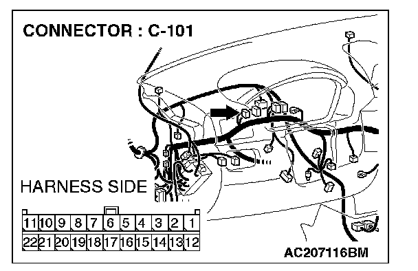
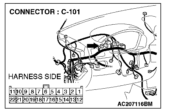
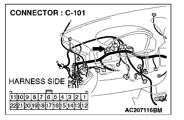
STEP 17. Check the CAN_H line (communication line only) between joint connector 4. and multi-center display unit (middle-grade type) connector for short to ground. Measure the resistance at joint connector 4. C-101.CAUTION: A digital multimeter should be used. For details refer to "Service Precautions".
CAUTION: The test wiring harness should be used. For details refer to "Service Precautions".

1. Disconnect joint connector 4. C-101 and multi-center display unit (middle-grade type) connector C-06, and measure the resistance at the wiring harness side of joint connector 4. C-101.
2. Turn the ignition switch to the "LOCK" (OFF) position.
CAUTION: Disconnect the negative battery terminal. For details refer to "Service Precautions".
3. Disconnect the negative battery terminal.
4. Measure the resistance between joint connector 4. terminal 19 and body ground.
OK: 1 kOhm or more
CAUTION: Strictly observe the specified wiring harness repair procedure. For details refer to "Precautions On How To Repair The CAN Bus Lines".
Q: Does the resistance measure 1 kOhm or more?
YES:
NO:
STEP 18. Check the CAN_H line (communication line only) between joint connector 4. and the data link connector for short to ground. Measure the resistance at joint connector 4. C-101.
CAUTION: A digital multimeter should be used. For details refer to "Service Precautions".
CAUTION: The test wiring harness should be used. For details refer to "Service Precautions".
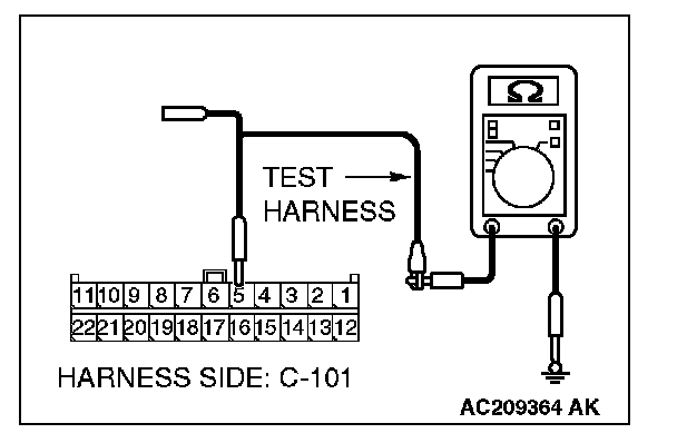
1. Disconnect joint connector 4. C-101, and measure the resistance at the wiring harness side of joint connector 4. C-101.
2. Turn the ignition switch to the "LOCK" (OFF) position.
CAUTION: Disconnect the negative battery terminal. For details refer to "Service Precautions".
3. Disconnect the negative battery terminal.
4. Measure the resistance between joint connector 4. terminal 16 and body ground.
OK: 1 kOhm or more
CAUTION: Strictly observe the specified wiring harness repair procedure. For details refer to "Precautions On How To Repair The CAN Bus Lines".
Q: Does the resistance measure 1 kOhm or more?
YES:
NO:
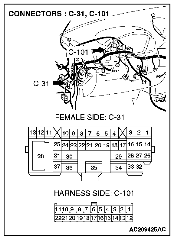
STEP 19. Check the CAN_H line (communication line only) between intermediate connector C-31 and joint connector 4. for short to ground. Measure the resistance at joint connector 4. C-101.
CAUTION: A digital multimeter should be used. For details refer to "Service Precautions".
CAUTION: The test wiring harness should be used. For details refer to "Service Precautions".
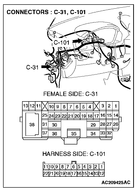
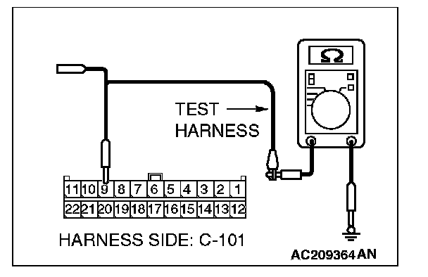
1. Disconnect intermediate connector C-31 and joint connector 4. C-101, and measure the resistance at the wiring harness side of joint connector 4. C-101.
2. Turn the ignition switch to the "LOCK" (OFF) position.
CAUTION: Disconnect the negative battery terminal. For details refer to "Service Precautions".
3. Disconnect the negative battery terminal.
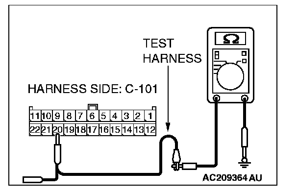
4. Measure the resistance between joint connector 4. terminal 20 and body ground.
OK: 1 kOhm or more
CAUTION: Strictly observe the specified wiring harness repair procedure. For details refer to "Precautions On How To Repair The CAN Bus Lines".
Q: Does the resistance measure 1 kOhm or more?
YES:
NO:
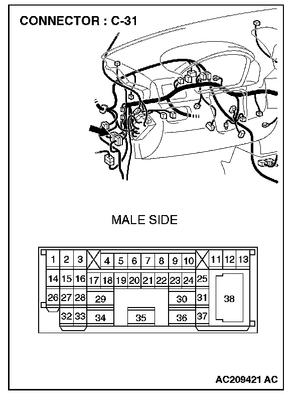
STEP 20. Check the CAN_H line (communication line only) between intermediate connector C-31 and the powertrain control module connector for short to ground. Measure the resistance at intermediate connector C-31.
CAUTION: A digital multimeter should be used. For details refer to "Service Precautions".
CAUTION: The test wiring harness should be used. For details refer to "Service Precautions".
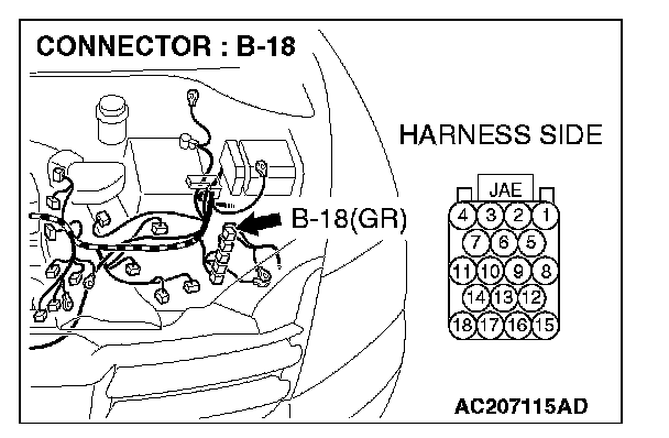
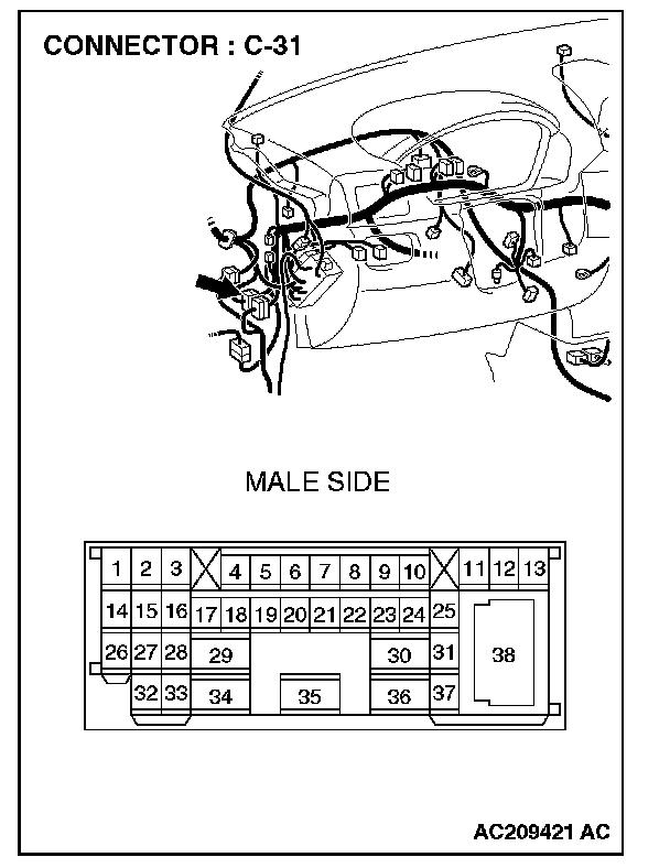
1. Disconnect powertrain control module connector B-18 and intermediate connector C-31, and measure the resistance at the male side of intermediate connector C-31 (at front wiring harness side).
2. Turn the ignition switch to the "LOCK" (OFF) position.
CAUTION: Disconnect the negative battery terminal. For details refer to "Service Precautions".
3. Disconnect the negative battery terminal.
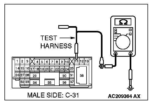
4. Measure the resistance between intermediate connector C-31 terminal 11 and body ground.
OK: 1 kOhm or more
CAUTION: Strictly observe the specified wiring harness repair procedure. For details refer to "Precautions On How To Repair The CAN Bus Lines".
Q: Does the resistance measure 1 kOhm or more?
YES:
NO:
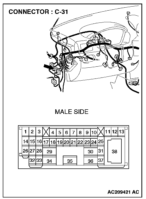
STEP 21. Check intermediate connector C-31 for loose, corroded or damaged terminals, or terminals pushed back in the connector.
CAUTION: The strand end of the twist wire should be within 10 cm from the connector. For details refer to "Service Precautions".
Q: Is intermediate connector C-31 in good condition?
YES: Go to Step 22.
NO: Repair the damaged parts.
STEP 22. Check the CAN_L-side bus line (communication line including ECUs) of the front wiring harness for short to ground. Measure the resistance at intermediate connector C-31.
CAUTION: A digital multimeter should be used. For details refer to "Service Precautions".
CAUTION: The test wiring harness should be used. For details refer to "Service Precautions".

1. Disconnect intermediate connector C-31, and measure the resistance at the male side (at front wiring harness side).
2. Turn the ignition switch to the "LOCK" (OFF) position.
CAUTION: Disconnect the negative battery terminal. For details refer to "Service Precautions".
3. Disconnect the negative battery terminal.
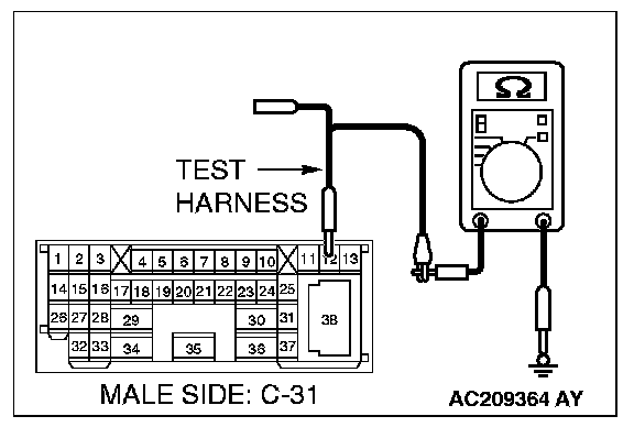
4. Measure the resistance between intermediate connector C-31 terminal 12 and body ground.
OK: 1 kOhm or more
Q: Does the resistance measure 1 kOhm or more?
YES:
NO:
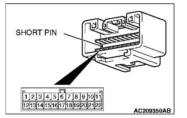
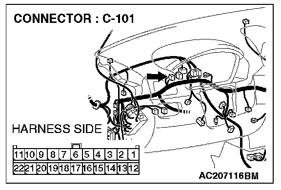
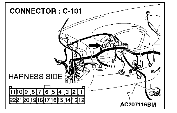
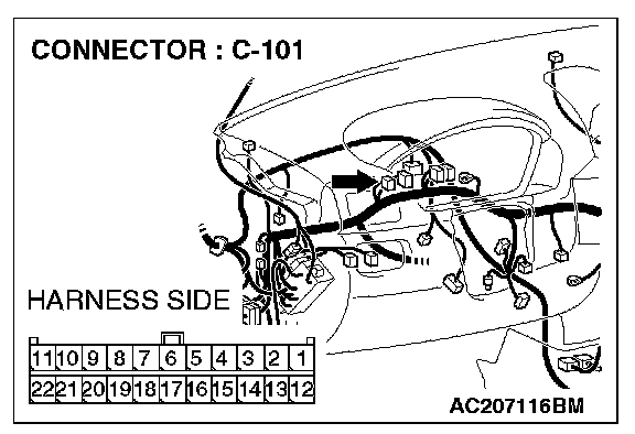
STEP 23. Check joint connector 4. C-101 for loose, corroded or damaged terminals, or terminals pushed back in the connector.
CAUTION: The strand end of the twist wire should be within 10 cm from the connector. For details refer to "Service Precautions".
Check the joint connector at the wiring harness side for loose, corroded or damaged terminals, or terminals pushed back in the connector, and also check the short pin behind the connector for corrosion, deformation and delamination.
Q: Is joint connector 4. C-101 in good condition?
YES: Go to Step 24.
NO: Repair the damaged parts. Replace the joint connector as necessary.
STEP 24. Check the CAN_L line (communication line including the combination meter) between joint connector 4. and the combination meter connector for short to ground. Measure the resistance at joint connector 4. C-101.
CAUTION: A digital multimeter should be used. For details refer to "Service Precautions".
CAUTION: The test wiring harness should be used. For details refer to "Service Precautions".

1. Disconnect joint connector 4. C-101, and measure the resistance at the wiring harness side of joint connector 4. C-101.
2. Turn the ignition switch to the "LOCK" (OFF) position.
CAUTION: Disconnect the negative battery terminal. For details refer to "Service Precautions".
3. Disconnect the negative battery terminal.
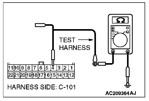
4. Measure the resistance between joint connector 4. terminal 4 and body ground.
OK: 1 kOhm or more
Q: Does the resistance measure 1 kOhm or more?
YES:
NO:
STEP 25. Check the CAN_L line (communication line only) between joint connector 4. and the combination meter connector for short to ground. Measure the resistance at joint connector 4. C-101.
CAUTION: A digital multimeter should be used. For details refer to "Service Precautions".
CAUTION: The test wiring harness should be used. For details refer to "Service Precautions".
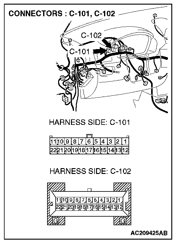
1. Disconnect joint connector 4. C-101 and combination meter connector C-102, and measure the resistance at the wiring harness side of joint connector 4. C-101.
2. Turn the ignition switch to the "LOCK" (OFF) position.
CAUTION: Disconnect the negative battery terminal. For details refer to "Service Precautions".
3. Disconnect the negative battery terminal.
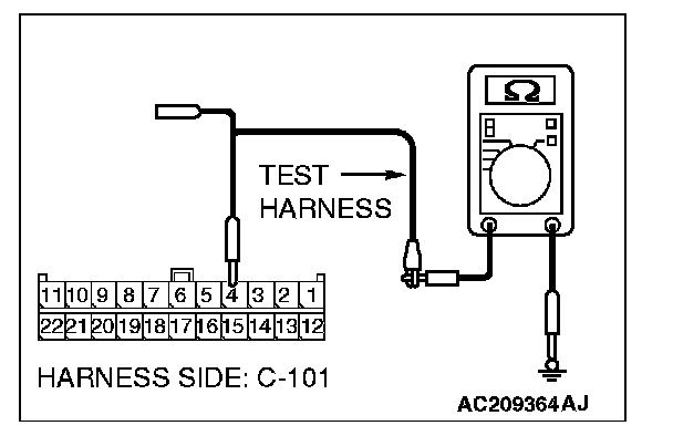
4. Measure the resistance between joint connector 4. terminal 4 and body ground.
OK: 1 kOhm or more
CAUTION: Strictly observe the specified wiring harness repair procedure. For details refer to "Precautions On How To Repair The CAN Bus Lines".
Q: Does the resistance measure 1 kOhm or more?
YES:
NO:
STEP 26. Check the CAN_L line (communication line including the ETACS-ECU) between joint connector 4. and the ETACS-ECU connector for short to ground. Measure the resistance at joint connector 4. C-101.
CAUTION: A digital multimeter should be used. For details refer to "Service Precautions".
CAUTION: The test wiring harness should be used. For details refer to "Service Precautions".

1. Disconnect joint connector 4. C-101, and measure the resistance at the wiring harness side of joint connector 4. C-101.
2. Turn the ignition switch to the "LOCK" (OFF) position.
CAUTION: Disconnect the negative battery terminal. For details refer to "Service Precautions".
3. Disconnect the negative battery terminal.
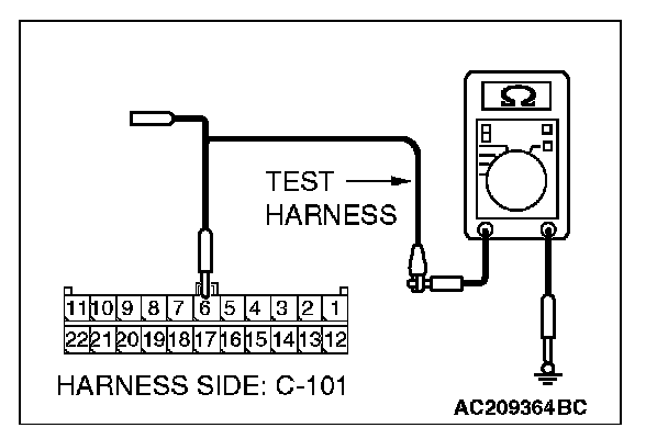
4. Measure the resistance between joint connector 4. terminal 6 and body ground.
OK: 1 kOhm or more
Q: Does the resistance measure 1 kOhm or more?
YES:
NO:
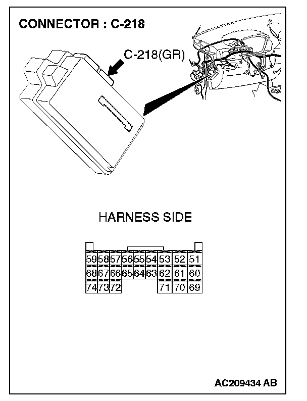
STEP 27. Check ETACS-ECU connector C-218 for loose, corroded or damaged terminals, or terminals pushed back in the connector.
CAUTION: The strand end of the twist wire should be within 10 cm from the connector. For details refer to "Service Precautions".
Q: Is ETACS-ECU connector C-218 in good condition?
YES: Go to Step 28.
NO: Repair the damaged parts.
STEP 28. Check the CAN_L line (communication line only) between joint connector 4. and ETACS-ECU connector for short to ground. Measure the resistance at joint connector 4. C-101.
CAUTION: A digital multimeter should be used. For details refer to "Service Precautions".
CAUTION: The test wiring harness should be used. For details refer to "Service Precautions".

1. Disconnect joint connector 4. C-101 and ETACS-ECU connector C-218, and measure the resistance at the wiring harness side of joint connector 4. C-101.
2. Turn the ignition switch to the "LOCK" (OFF) position.
CAUTION: Disconnect the negative battery terminal. For details refer to "Service Precautions".
3. Disconnect the negative battery terminal.
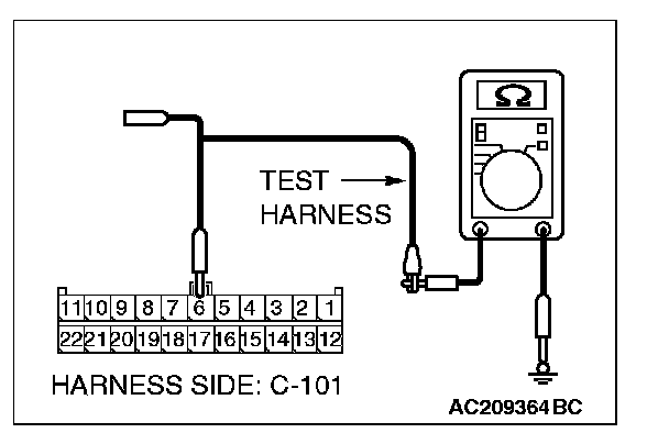
4. Measure the resistance between joint connector 4. terminal 6 and body ground.
OK: 1 kOhm or more
CAUTION: Strictly observe the specified wiring harness repair procedure. For details refer to "Precautions On How To Repair The CAN Bus Lines".
Q: Does the resistance measure 1 kOhm or more?
YES:
NO:
STEP 29. Check the CAN_L line (communication line including the A/C-ECU) between joint connector 4. and the A/C-ECU connector for short to ground. Measure the resistance at joint connector 4. C-101.
CAUTION: A digital multimeter should be used. For details refer to "Service Precautions".
CAUTION: The test wiring harness should be used. For details refer to "Service Precautions".
1. Disconnect joint connector 4. C-101, and measure the resistance at the wiring harness side of joint connector 4. C-101.
2. Turn the ignition switch to the "LOCK" (OFF) position.
CAUTION: Disconnect the negative battery terminal. For details refer to "Service Precautions".
3. Disconnect the negative battery terminal.
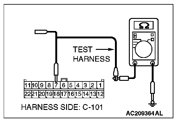
4. Measure the resistance between joint connector 4. terminal 7 and body ground.
OK: 1 kOhm or more
Q: Does the resistance measure 1 kOhm or more?
YES:
NO:
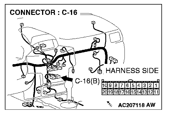
STEP 30. Check A/C-ECU connector C-16 for loose, corroded or damaged terminals, or terminals pushed back in the connector.
CAUTION: The strand end of the twist wire should be within 10 cm from the connector. For details refer to "Service Precautions".
Q: Is A/C-ECU connector C-16 in good condition?
YES: Go to Step 31.
NO: Repair the damaged parts.
STEP 31. Check the CAN_L line (communication line only) between joint connector 4. and A/C-ECU connector for short to ground. Measure the resistance at joint connector 4. C-101.
CAUTION: A digital multimeter should be used. For details refer to "Service Precautions".
CAUTION: The test wiring harness should be used. For details refer to "Service Precautions".
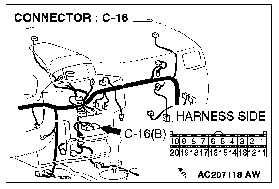

1. Disconnect joint connector 4. C-101 and A/C-ECU connector C-16, and measure the resistance at the wiring harness side of joint connector 4. C-101.
2. Turn the ignition switch to the "LOCK" (OFF) position.
CAUTION: Disconnect the negative battery terminal. For details refer to "Service Precautions".
3. Disconnect the negative battery terminal.
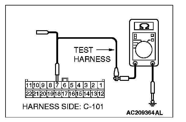
4. Measure the resistance between joint connector 4. terminal 7 and body ground.
OK: 1 kOhm or more
CAUTION: Strictly observe the specified wiring harness repair procedure. For details refer to "Precautions On How To Repair The CAN Bus Lines".
Q: Does the resistance measure 1 kOhm or more?
YES:
NO:
STEP 32. Check the CAN_L line (communication line including the middle-grade multi-center display) between joint connector 4. and middle-grade multi-center display connector for short to ground. Measure the resistance at joint connector 4. C-101.
CAUTION: A digital multimeter should be used. For details refer to "Service Precautions".
CAUTION: The test wiring harness should be used. For details refer to "Service Precautions".
1. Disconnect joint connector 4. C-101, and measure the resistance at the wiring harness side of joint connector 4. C-101.
2. Turn the ignition switch to the "LOCK" (OFF) position.
CAUTION: Disconnect the negative battery terminal. For details refer to "Service Precautions".
3. Disconnect the negative battery terminal.
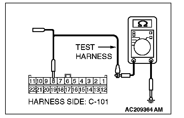
4. Measure the resistance between joint connector 4. terminal 8 and body ground.
OK: 1 kOhm or more
Q: Does the resistance measure 1 kOhm or more?
YES:
NO:
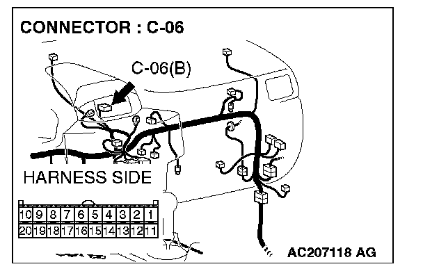
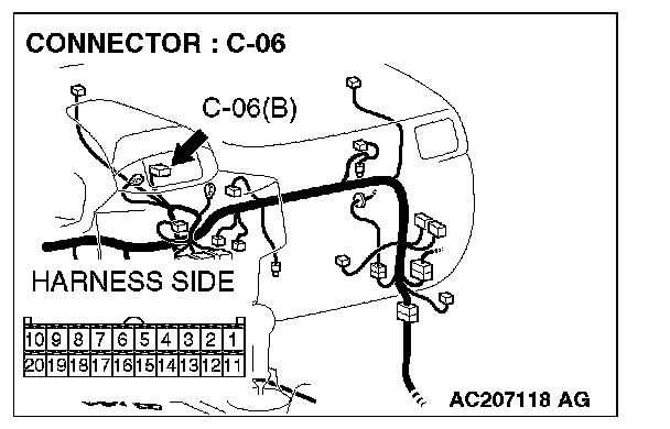
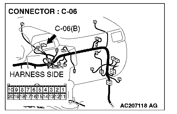
STEP 33. Check multi-center display unit (middle-grade type) connector C-06 for loose, corroded or damaged terminals, or terminals pushed back in the connector.
CAUTION: The strand end of the twist wire should be within 10 cm from the connector. For details refer to "Service Precautions".
Q: Is multi-center display unit (middle-grade type) connector C-06 in good condition?
YES: Go to Step 34.
NO: Repair the damaged parts.
STEP 34. Check the CAN_L line (communication line only) between joint connector 4. and multi-center display unit (middle-grade type) connector for short to ground. Measure the resistance at joint connector 4. C-101.
CAUTION: A digital multimeter should be used. For details refer to "Service Precautions".
CAUTION: The test wiring harness should be used. For details refer to "Service Precautions".
1. Disconnect joint connector 4. C-101 and multi-center display unit (middle-grade type) connector C-06, and measure the resistance at the wiring harness side of joint connector 4. C-101.
2. Turn the ignition switch to the "LOCK" (OFF) position.
CAUTION: Disconnect the negative battery terminal. For details refer to "Service Precautions".
3. Disconnect the negative battery terminal.
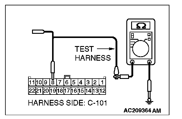
4. Measure the resistance between joint connector 4. terminal 8 and body ground.
OK: 1 kOhm or more
CAUTION: Strictly observe the specified wiring harness repair procedure. For details refer to "Precautions On How To Repair The CAN Bus Lines".
Q: Does the resistance measure 1 kOhm or more?
YES:
NO:
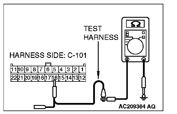
STEP 35. Check the CAN_L line (communication line only) between joint connector 4. and the data link connector for short to ground. Measure the resistance at joint connector 4. C-101.
CAUTION: A digital multimeter should be used. For details refer to "Service Precautions".
CAUTION: The test wiring harness should be used. For details refer to "Service Precautions".
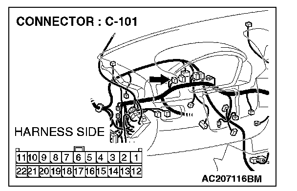
1. Disconnect joint connector 4. C-101, and measure the resistance at the wiring harness side of joint connector 4. C-101.
2. Turn the ignition switch to the "LOCK" (OFF) position.
CAUTION: Disconnect the negative battery terminal. For details refer to "Service Precautions".
3. Disconnect the negative battery terminal.
4. Measure the resistance between joint connector 4. terminal 5 and body ground.
OK: 1 kOhm or more
CAUTION: Strictly observe the specified wiring harness repair procedure. For details refer to "Precautions On How To Repair The CAN Bus Lines".
Q: Does the resistance measure 1 kOhm or more?
YES:
NO:
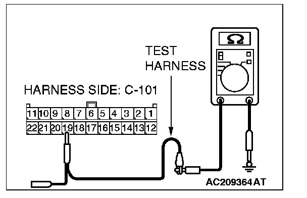
STEP 36. Check the CAN_L line (communication line only) between intermediate connector C-31 and joint connector 4. for short to ground. Measure the resistance at joint connector 4. C-101.
CAUTION: A digital multimeter should be used. For details refer to "Service Precautions".
CAUTION: The test wiring harness should be used. For details refer to "Service Precautions".
1. Disconnect intermediate connector C-31 and joint connector 4. C-101, and measure the resistance at the wiring harness side of joint connector 4. C-101.
2. Turn the ignition switch to the "LOCK" (OFF) position.
CAUTION: Disconnect the negative battery terminal. For details refer to "Service Precautions".
3. Disconnect the negative battery terminal.
4. Measure the resistance between joint connector 4. terminal 9 and body ground.
OK: 1 kOhm or more
CAUTION: Strictly observe the specified wiring harness repair procedure. For details refer to "Precautions On How To Repair The CAN Bus Lines".
Q: Does the resistance measure 1 kOhm or more?
YES:
NO:
STEP 37. Check the CAN_H line (communication line only) between intermediate connector C-31 and the powertrain control module connector for short to ground. Measure the resistance at intermediate connector C-31.
CAUTION: A digital multimeter should be used. For details refer to "Service Precautions".
CAUTION: The test wiring harness should be used. For details refer to "Service Precautions".
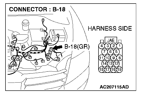
1. Disconnect powertrain control module connector B-18 and intermediate connector C-31, and measure the resistance at the male side of intermediate connector C-31 (at front wiring harness side).
2. Turn the ignition switch to the "LOCK" (OFF) position.
CAUTION: Disconnect the negative battery terminal. For details refer to "Service Precautions".
3. Disconnect the negative battery terminal.
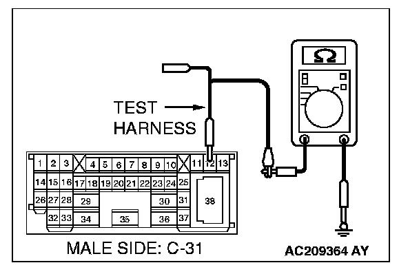
4. Measure the resistance between intermediate connector C-31 terminal 12 and body ground.
OK: 1 kOhm or more
CAUTION: Strictly observe the specified wiring harness repair procedure. For details refer to "Precautions On How To Repair The CAN Bus Lines".
Q: Does the resistance measure 1 kOhm or more?
YES:
NO: