Audio System/Multi-Center Display - Troubleshooting
No: TSB-03-54-006DATE: June, 2003
MODEL: 2004 Endeavor
SUBJECT:
AUDIO SYSTEM & MULTI-CENTER DISPLAY TROUBLESHOOTING
PURPOSE
This bulletin contains condensed diagnostic information and quick-reference troubleshooting charts for servicing the audio systems with multi-center display used in the 2004 Endeavor. The procedures in this bulletin are intended to supplement the procedures in Group 54 of the service manual, to help diagnose some typical failures and problems.
BACKGROUND INFORMATION
The audio system used in the Endeavor uses "M-Bus" technology for communication between the components and the multi-center display. Adjusting some audio component controls has no direct effect on the related system functions. Many audio controls send signals from the component to the multi-center display, where the display processes the signal and then sends the actual control signal back to the audio component(s) where the proper function is activated. A suspected radio problem or failure may actually be caused by a malfunctioning multi-center display, or vice versa.
AFFECTED VEHICLES
2004 Endeavor
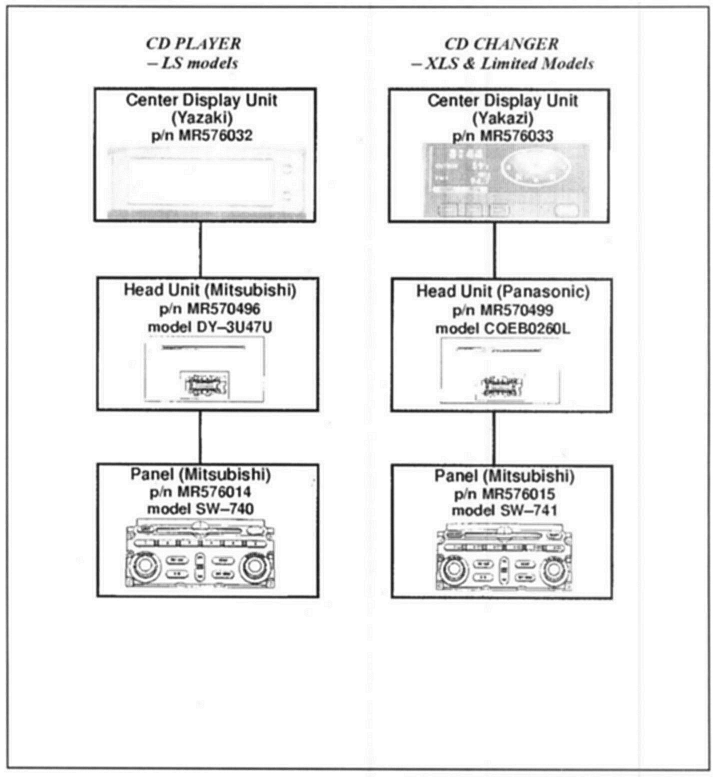
COMPONENT COMBINATIONS
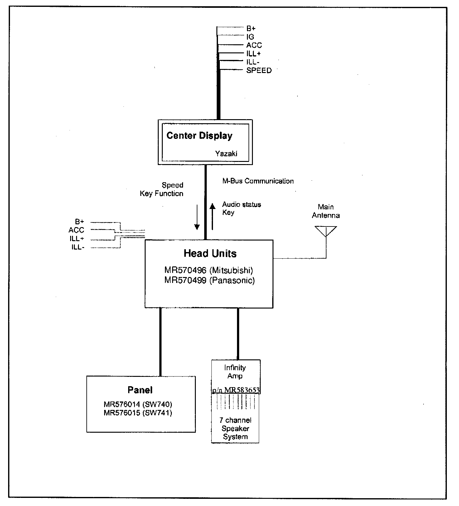
SYSTEM DIAGRAM
PROCEDURES
A.Self-Diagnosis Functions
The system has the following built-in, self-diagnosis functions to assist in locating the problem area.
1. SPEAKER DIAGNOSIS FUNCTION
Checks each output channel (one at a time) to verity proper operation of the amplifier, speaker wires, and the speakers. NOTE: There is no check for the center speaker in Infinity systems.
^ This feature improves efficiency when checking audio system output difficulties. It is able to check the signal path from the head unit all the way to the speaker. It can check the amplifier, the cable on Infinity systems, speakers wires and the speakers for proper operation.
^ The head unit will send out a test tone to each channel separately (one channel at a time). It will indicate on the display which channel is sending out the tone. The corresponding speaker should play the tone.
^ There are two different test tones (frequencies), one for the tweeter and one for the woofer. The speaker diagnosis function works in the test mode. Before using this function, set up the test mode using the following steps:
a. Test Mode Entry
CONDITION OF HEAD UNIT
1. Ignition key must be in ACC position.
2. Turn on audio system.
3. Turn off audio system (you now have 60 seconds to perform the following steps)
TEST MODE START-UP
1. Push and release the "Channel 1" button.
2. Push and release the "Tune/Seek DOWN" button
3. Push and release the "Tune/Seek UP" button
4. Push and release the "Channel 6" button. The test mode will now start.
NOTE:
The above operation must be done within 60 seconds after the head unit is turned OFF. You will not be able to put the radio into the test mode after 60 seconds.
If a mistake is made during the entry into the test mode or the 60 seconds run out, push the power button on the head unit and turn it ON and then OFF again. Then you can re-start test mode from the beginning.
b. Test Mode Operation
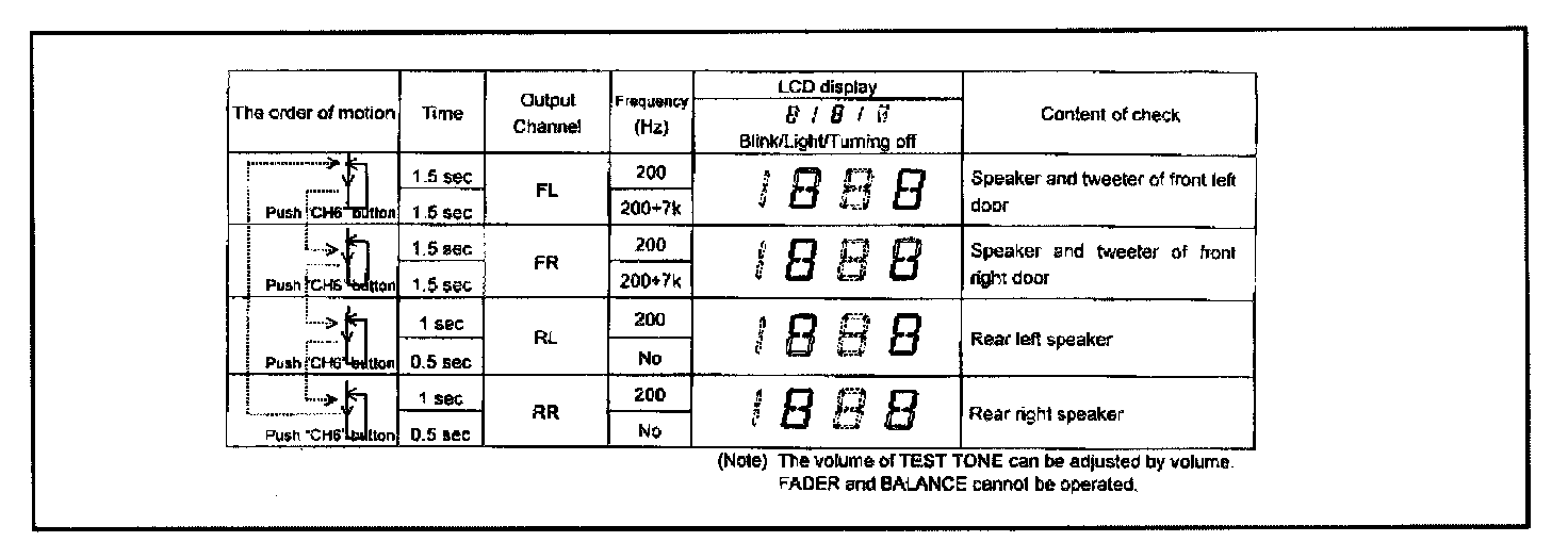
The test mode operates as shown in the TEST MODE chart.
^ The test tone can be repeated at the specified frequency and time for each speaker.
^ The following output channel can be switched by pushing the "Channel 6" button.
c. CANCEL Test Mode
The test mode can be canceled by the following procedure:
1. Push any button except the "Channel 6" button.
(Pushing a mode button such as FM/AM or CD will switch off that mode.)
2. Turn the ignition key OFF.
2."NO DISPLAY" OPERATION CHECK FUNCTION
The head unit has a function that will allow it to work by itself without connection to the center display. This function can be used to confirm proper operation without the display. If there is a problem with the display, the head unit may also appear to have a problem. This function allows the head unit to be checked regardless of the condition of the display.
a. Conditions to start the operation check function:
1. Key must be in the OFF position.
b. Operation Procedure - To start the operation check function:
1. Push and hold the "FM/AM" and "Power" buttons at the same time.
2. While holding the two buttons, turn on the key. The Operation Check Function will start, to confirm if there is no problem at the head unit side when there is no display.
B. Audio System Troubleshooting
1. DISCONNECTING THE BATTERY
The audio system stores in memory the preset radio stations, stations selected during a search, and volume/tone/balance positions. When the radio loses main power, this data is kept in memory for approximately one hour. Note the memory data before disconnecting the battery, unplugging the 14-pin connector, or pulling the IOD plug.
2. MULTI-FUNCTION CENTER DISPLAY TERMINAL STATUS
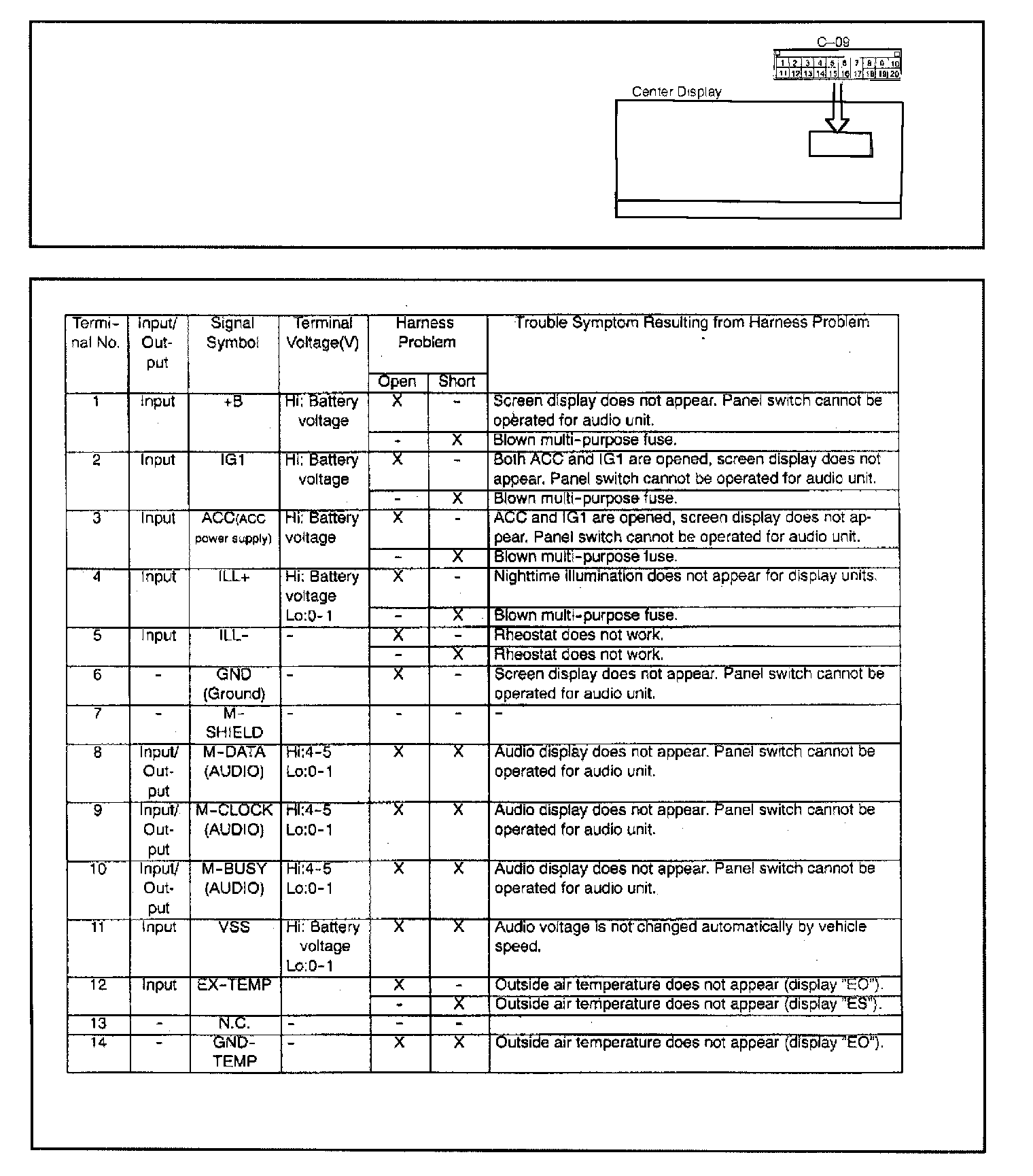
The chart shows center display terminal status and possible cause/effect information.
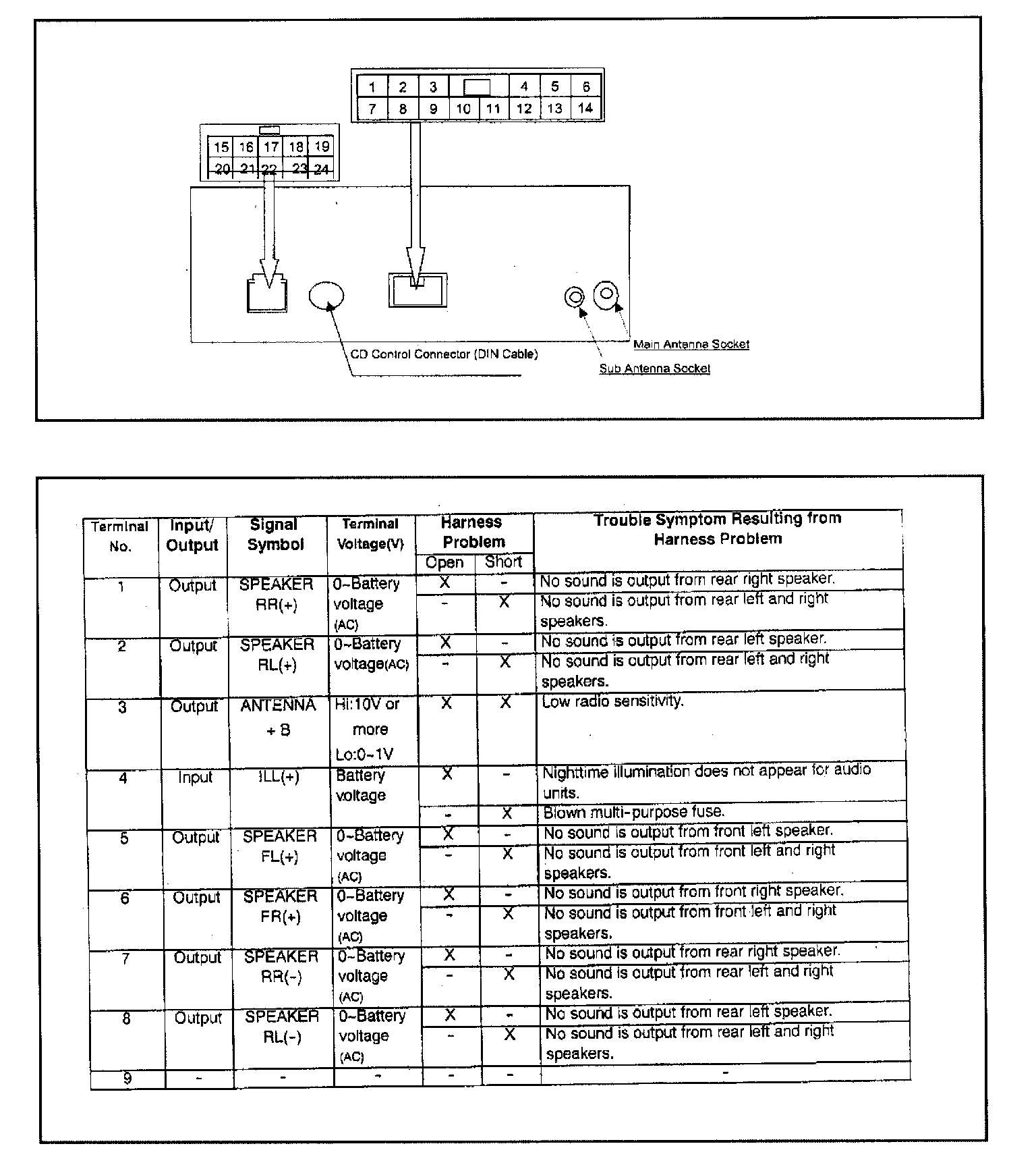
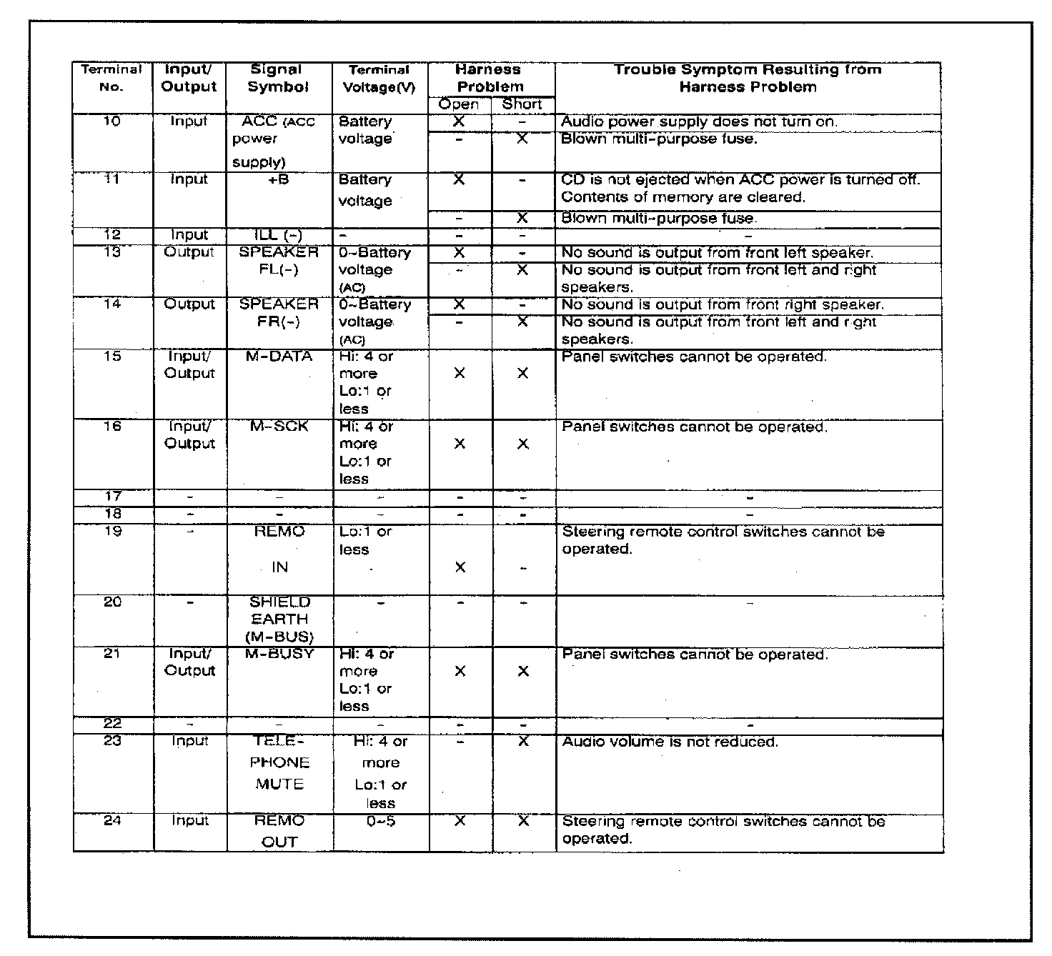
3. Audio System Head Unit Terminal Status
4. INSPECTION PROCEDURES
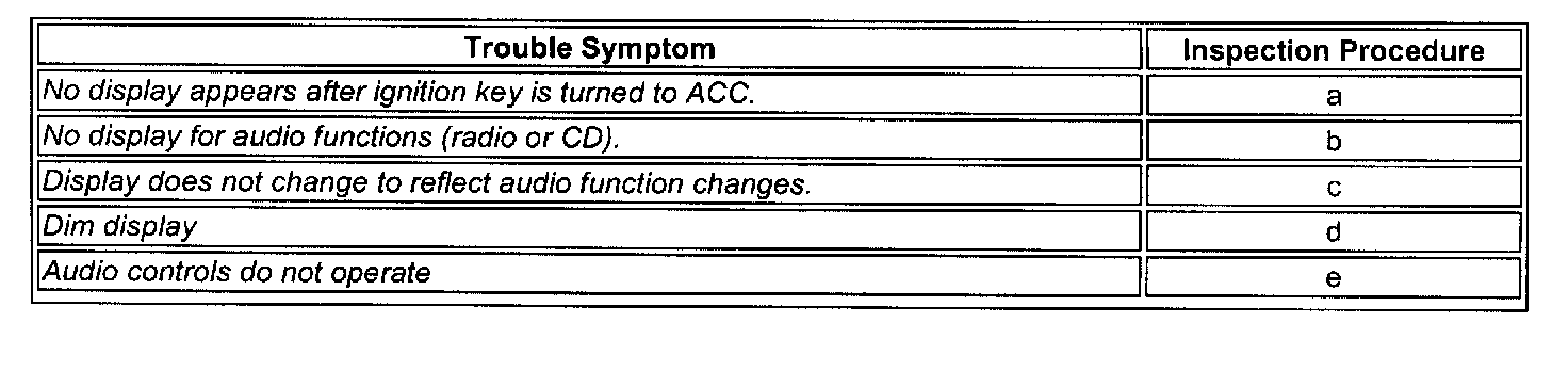
Trouble Symptom Inspection Chart - Before troubleshooting, perform the self-diagnosis functions provided earlier in this bulletin.
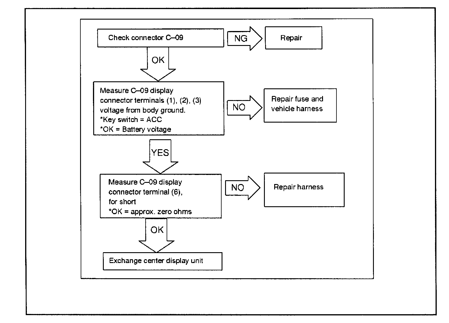
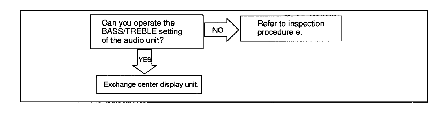
a. Display Not Working
Conditions:
1. Ignition key in ACC or ON position.
2. No display appears and none of the audio system functions respond.
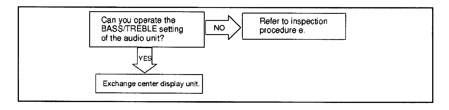
b. No Radio Display (Clock Display Works)
Conditions:
1. Ignition key in ACC or ON position.
2. No display appears.
3. Time display appears, but audio function displays do not appear.
4. Approximately 30 seconds later, "E Com" error code appears.
5. Audio functions may be OK except for BASS/TREBLE setting.
c. Display Will Not Change (Frozen I Locked Up)
Conditions:
1. Ignition key in ACC or ON position.
2. Audio mode is set to radio, CD player, or CD changer (not power off) and the sound can be heard.
3. Time display appears, but audio function displays do not appear.
4. Approximately 30 seconds later, '1E Corn" error code appears.
5. Audio functions may be OK except for BASS/TREBLE setting.
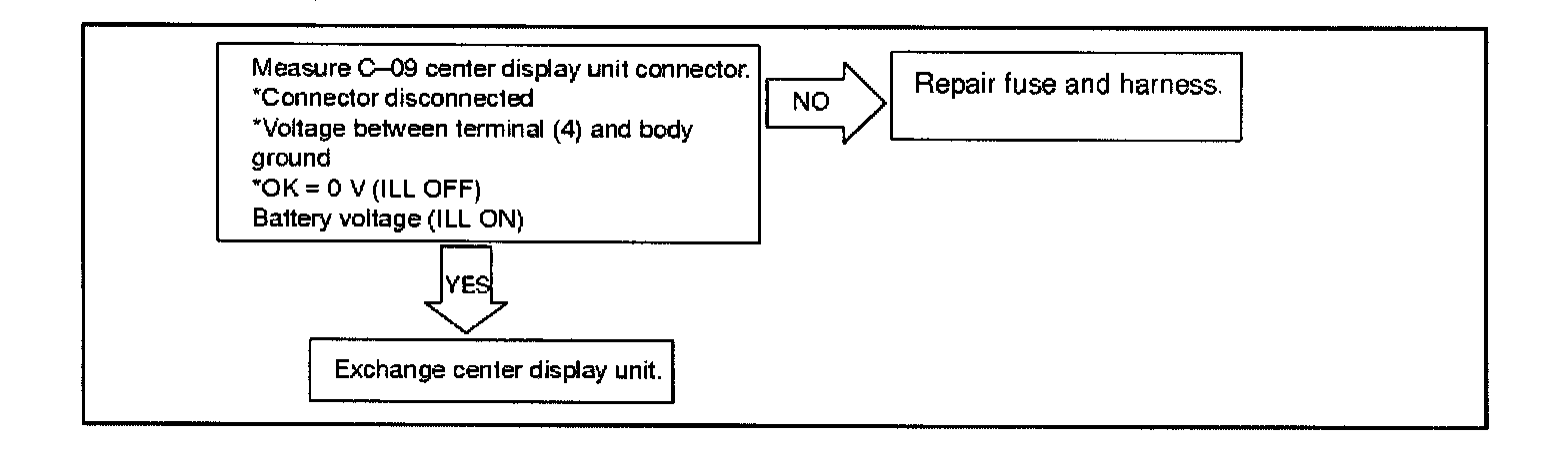
d. DIM DISPLAY
Conditions:
1. Ignition key in ACC or ON position.
2. Brightness of the display does not change by pressing ILL on/off.
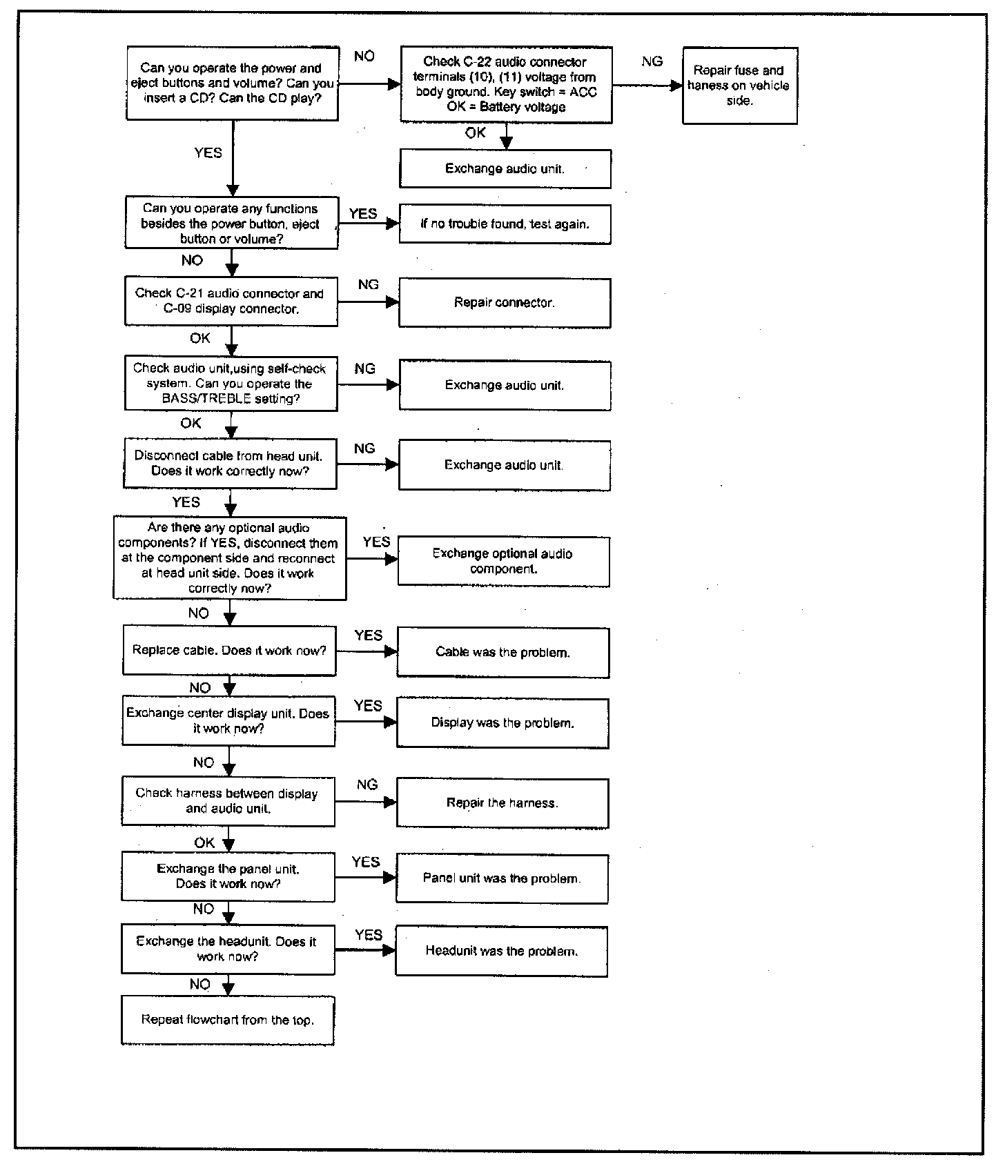
e. No Response From Audio Function Controls
Ignition key in ACC or ON position. Some controls cannot be operated. Display of time appears.
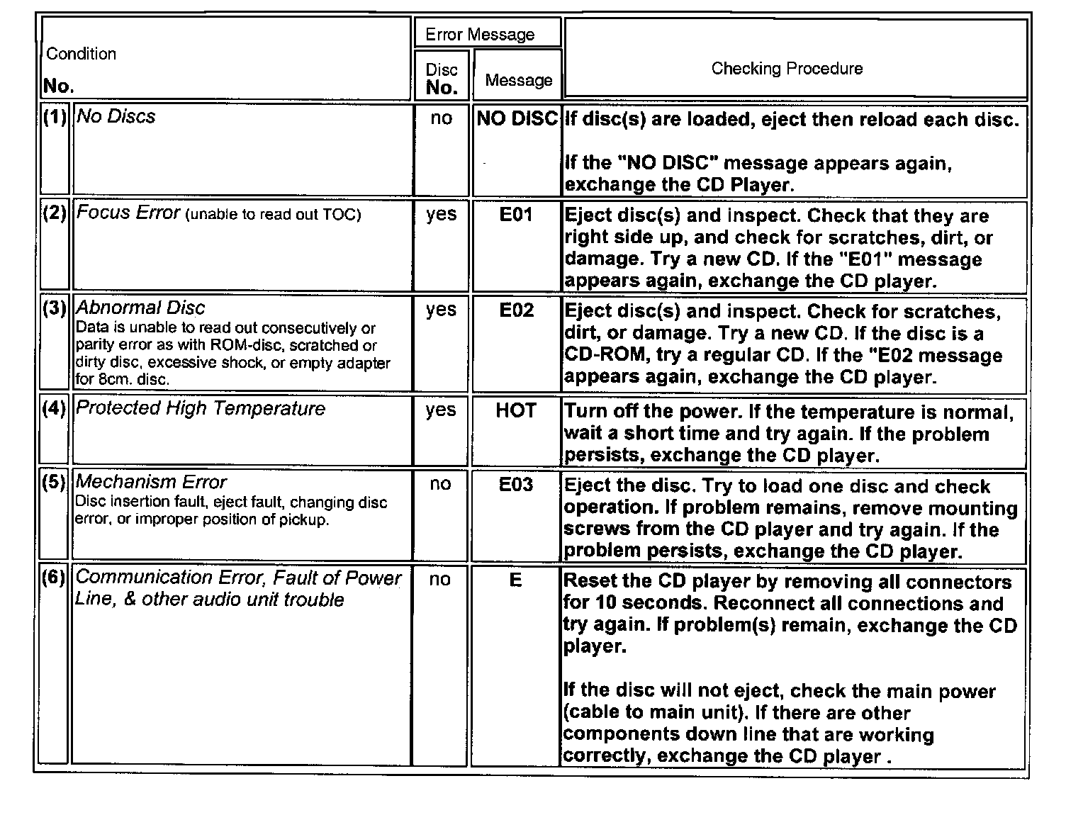
CD Player Error Messages
WARRANTY INFORMATION
Normal audio system warranty exchange procedures apply to all Endeavor audio components including the control panel. Refer to Warranty Bulletin WB2004-002 for details.
Refer to Appendix A in the Warranty Policy and Procedure Manual for details on audio unit exchanges. MMNA Authorized Audio/Center Display Unit Exchange Centers are listed at the end of this bulletin. Dealers must call the appropriate exchange center when a customer's unit is diagnosed with a problem requiring replacement. The exchange center will ship a replacement unit to the dealership, usually within 48 hours. Immediately after the exchange unit is installed, return the defective unit with the completed diagnostic checklist to the supplying exchange center in the same shipping box that the replacement unit came in. Failure to return the replaced unit will result in the dealership being billed for the replacement unit and suspended from futher exchange shipments until the invoice is paid or the unit returned.
IMPORTANT
All replacement audio units and center displays contain a copy of a diagnostic checklist. If unit replacement is necessary, the checklist must be completed and returned with the old unit. Missing or incomplete checklists will result in a charge-back of the related warranty claim.
MMNA Authorized Audio/Center Display Unit Exchange Centers
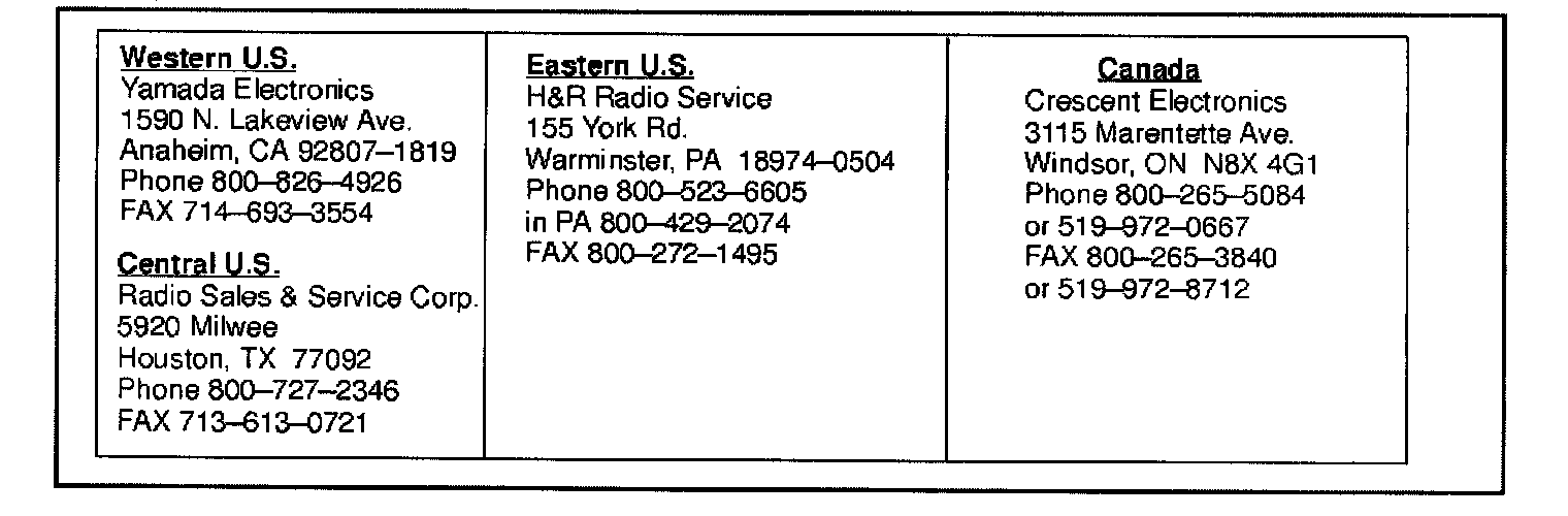
MITSUBISHI AUDIO CHASSIS AND ALL CONTROL PANELS
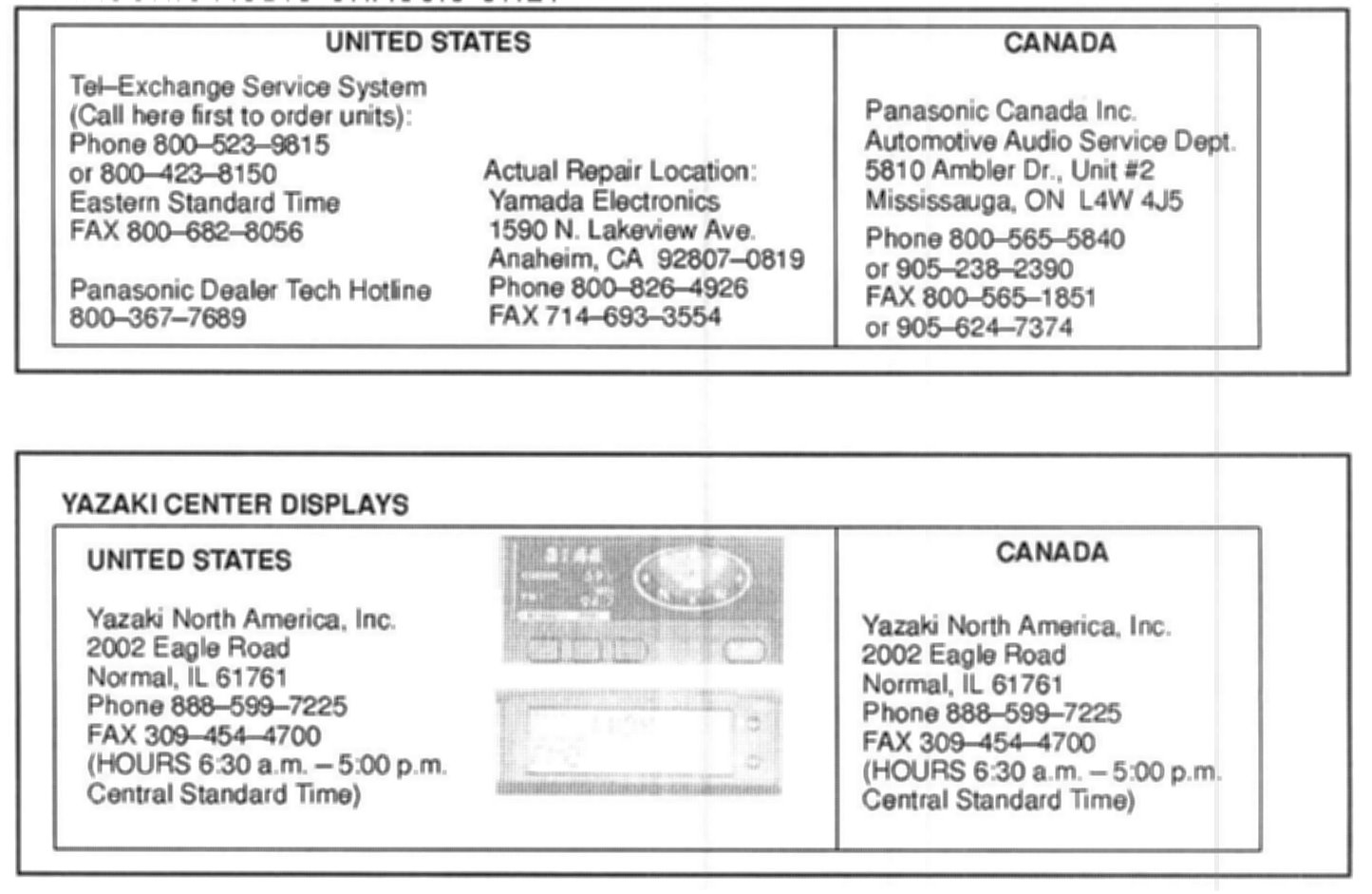
PANASONIC AUDIO CHASSIS ONLY