Removal and Replacement
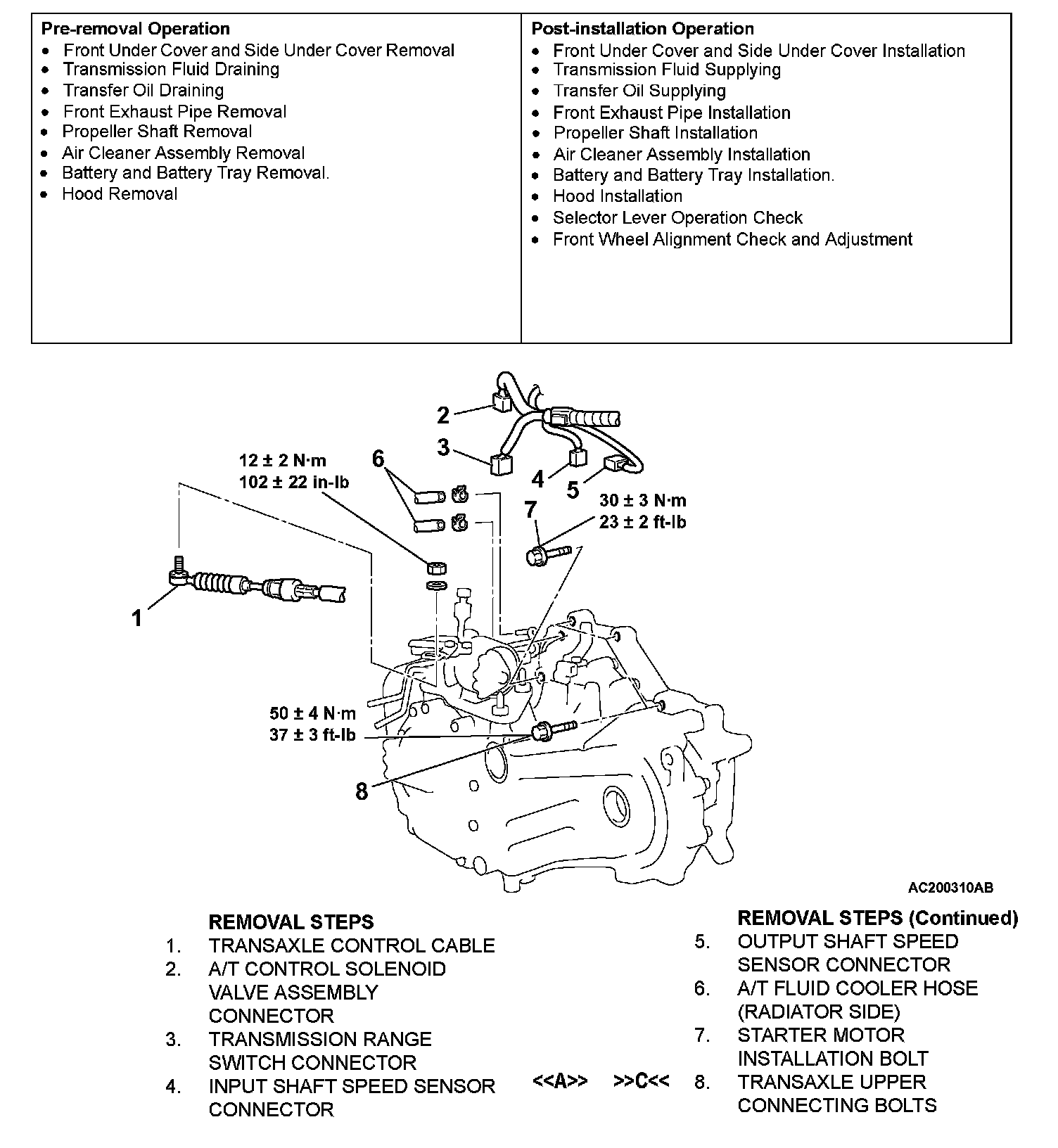
Part 1 Of 2:
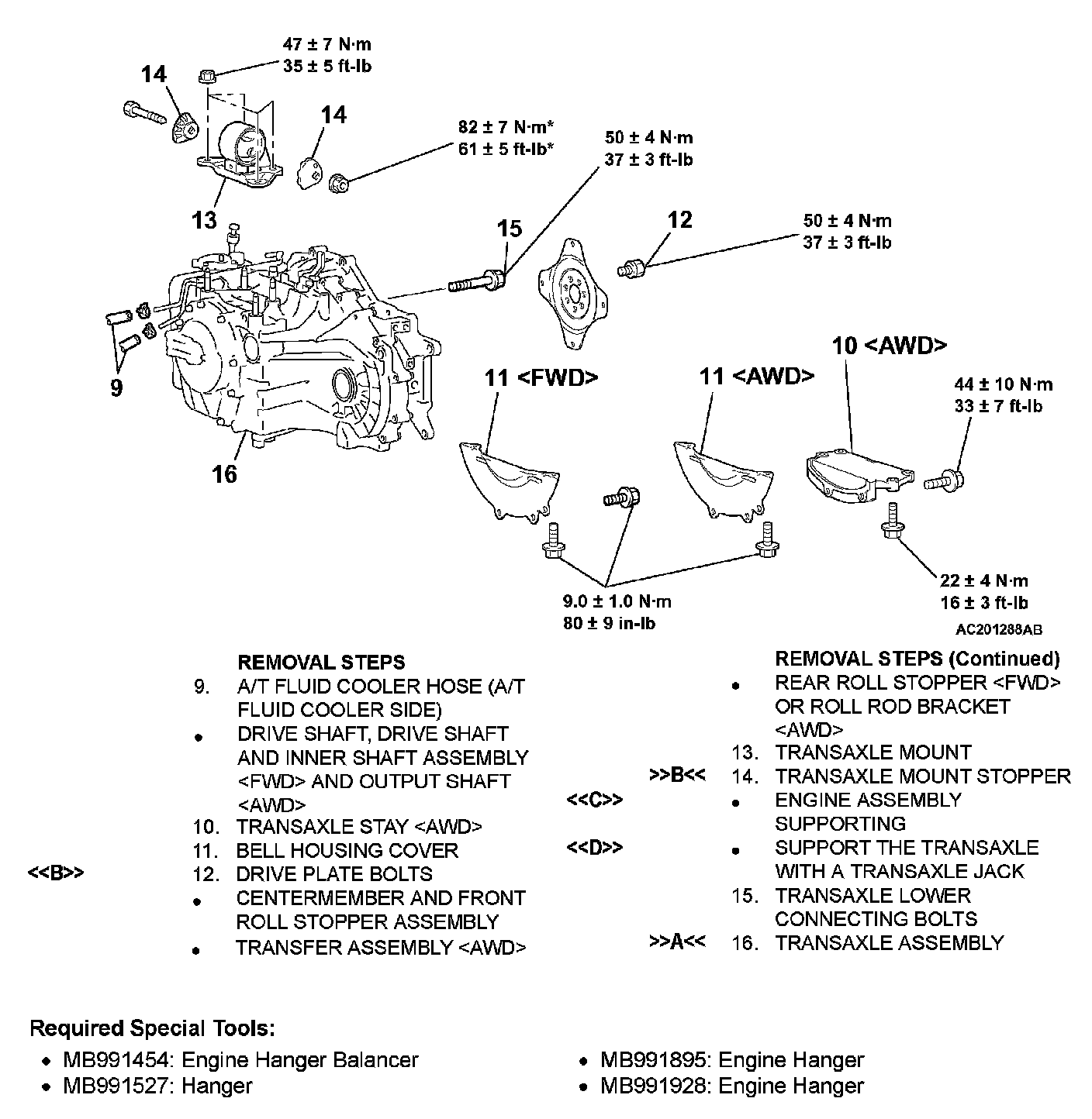
Part 2 Of 2:
TRANSAXLE ASSEMBLY
REMOVAL AND INSTALLATION
CAUTION: *: Indicates parts which should be temporarily tightened, and then fully tightened after placing the vehicle on the ground and loading the full weight of the engine on the vehicle body.
Required Special Tools:
^ MB991454: Engine Hanger Balancer
^ MB991527: Hanger
^ MB991895: Engine Hanger
^ MB991928: Engine Hanger
REMOVAL SERVICE POINTS
<> TRANSAXLE ASSEMBLY UPPER PART COUPLING BOLTS REMOVAL
Do not fully unscrew the bolts from the trans-axle assembly.
Only loosen the bolts.
<> DRIVE PLATE BOLTS REMOVAL
1. Turn the crank shaft so that it is positioned to allow the drive plate bolt to be unscrewed.
2. Push in the torque converter into the transaxle side and make a point to ensure that the torque converter does not remain on the engine side.
<
Jack up the transaxle assembly gently and then remove the transaxle mounting.
<
1.
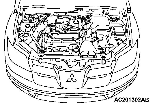
1. Set the special tool MB991895 to the front fender assembling bolt (A, B) and radiator upper insulator assembling bolt (C, D) inside the engine room, as shown in the figure of the instructions.
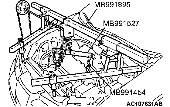
2. Set the special tools MB991454 and MB991527, support the engine transaxle assembly, and unscrew the transaxle assembly upper part coupling bolts that were priority loosened.
2.
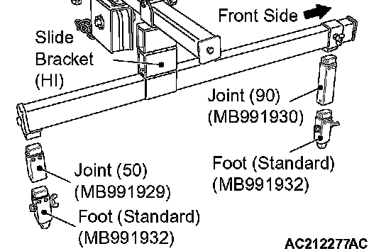
1. Assemble the engine hanger (special tool MB991928). Set following parts to the base hanger.
^ Slide bracket (Hi)
^ Foot (standard) (MB991932)
^ Joint (90) (MB991930)
^ Joint (50) (MB991929)
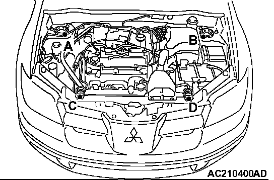
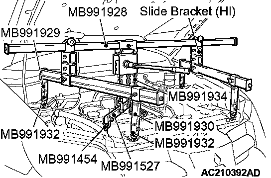
2. Set the special tool MB991895 to the strut mounting nuts (A, B) and radiator upper insulator assembling bolt (C, D) inside the engine room, as shown in the figure of the instructions.
NOTE: Adjust the engine hanger balance by sliding the slide bracket (Hi).
3. Set the special tools MB991454 and MB991895, support the engine transaxle assembly, and unscrew the transaxle assembly upper part coupling bolts that were priority loosened.
INSTALLATION SERVICE POINTS
>>A<< TRANSAXLE ASSEMBLY INSTALLATION
Thoroughly insert the torque converter into the trans-axle side then assemble the trans-axle assembly on the engine.
>>B<< TRANSAXLE MOUNT STOPPER INSTALLATION
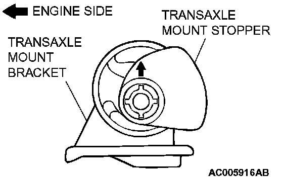
Install the transaxle mount stopper so that the arrow mark points as shown in the illustration.
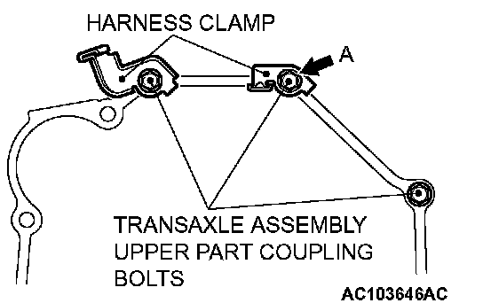
>>C<< TRANSAXLE ASSEMBLY UPPER PART COUPLING BOLTS INSTALLATION
Assemble the harness clamp as shown in the illustration of the instructions. The bolts A shown in the illustration of the instructions should then be tightened along with the grounding.