Part 3
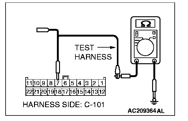
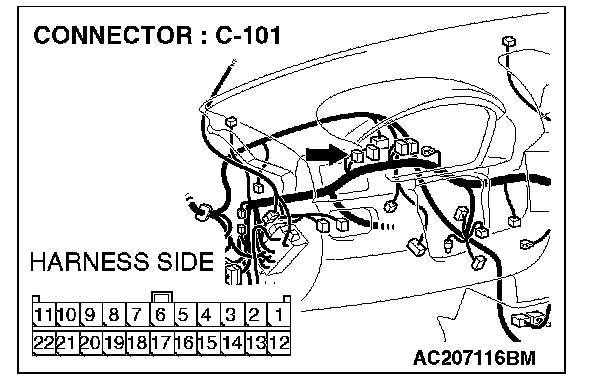
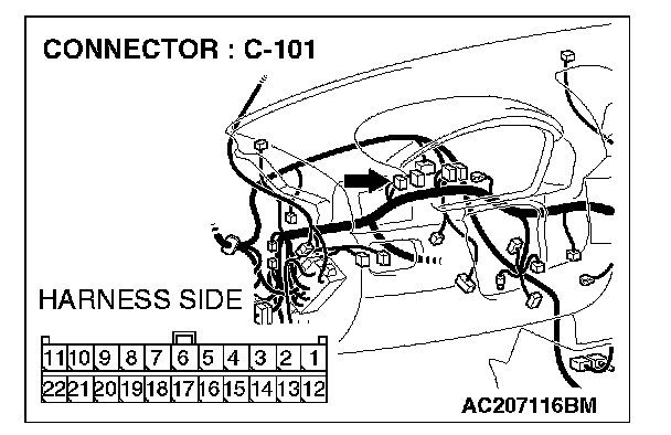
STEP 42.Check the CAN_L line (communication line including the A/C-ECU) between joint connector (4) and the A/C-ECU connector for short to ground. Measure the resistance at joint connector (4) C-101.CAUTION: A digital multimeter should be used. For details refer to Service Precautions/Vehicle Damage Warnings.
CAUTION: The test wiring harness should be used. For details refer to Service Precautions/Vehicle Damage Warnings.
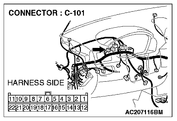
1. Disconnect joint connector (4) C-101, and measure the resistance at the wiring harness side of joint connector (4) C-101.
2. Turn the ignition switch to the "LOCK" (OFF) position.
CAUTION: Disconnect the negative battery terminal. For details refer to Service Precautions/Vehicle Damage Warnings.
3. Disconnect the negative battery terminal.
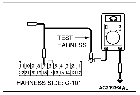
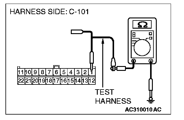
4. Measure the resistance between joint connector (4) terminal 7 and body ground.
OK: 1 kOhms or more
Q: Does the resistance measure 1 kOhms or more?
YES:
NO:
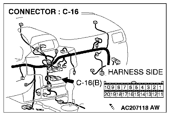
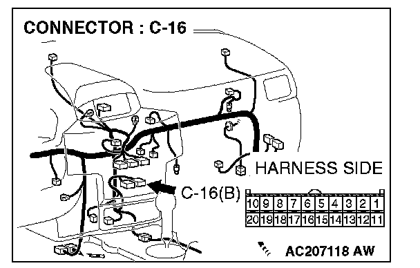
STEP 43. Check A/C-ECU connector C-16 for loose, corroded or damaged terminals, or terminals pushed back in the connector.
CAUTION: The strand end of the twist wire should be within 10 cm (4 inches) from the connector. For details refer to Service Precautions/Vehicle Damage Warnings.
Q: Is A/C-ECU connector C-16 in good condition?
YES: Go to Step 44.
NO: Repair the damaged parts.
STEP 44. Check the CAN_L line (communication line only) between joint connector (4) and A/C-ECU connector for short to ground. Measure the resistance at joint connector (4) C-101.
CAUTION: A digital multimeter should be used. For details refer to Service Precautions/Vehicle Damage Warnings.
CAUTION: The test wiring harness should be used. For details refer to Service Precautions/Vehicle Damage Warnings.

1. Disconnect joint connector (4) C-101 and A/C-ECU connector C-16, and measure the resistance at the wiring harness side of joint connector (4) C-101.
2. Turn the ignition switch to the "LOCK" (OFF) position.
CAUTION: Disconnect the negative battery terminal. For details refer to Service Precautions/Vehicle Damage Warnings.
3. Disconnect the negative battery terminal.
4. Measure the resistance between joint connector (4) terminal 7 and body ground.
OK: 1 kOhms or more
CAUTION: Strictly observe the specified wiring harness repair procedure. For details refer to Precautions on How to Repair The CAN Bus Lines.
Q: Does the resistance measure 1 kOhms or more?
YES:
NO:
STEP 45. Check the CAN_L line (communication line including the SRS-ECU) between joint connector (4) and the SRS-ECU connector for short to ground. Measure the resistance at joint connector (4) C-101.
CAUTION: A digital multimeter should be used. For details refer to Service Precautions/Vehicle Damage Warnings.
CAUTION: The test wiring harness should be used. For details refer to Service Precautions/Vehicle Damage Warnings.

1. Disconnect joint connector (4) C-101, and measure the resistance at the wiring harness side of joint connector (4) C-101.
2. Turn the ignition switch to the "LOCK" (OFF) position.
CAUTION: Disconnect the negative battery terminal. For details refer to Service Precautions/Vehicle Damage Warnings.
3. Disconnect the negative battery terminal.
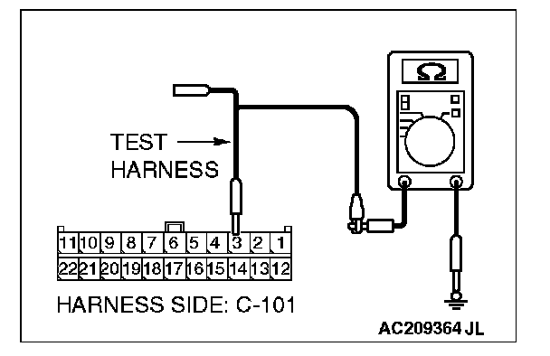
4. Measure the resistance between joint connector (4) terminal 3 and body ground.
OK: 1 kOhms or more
Q: Does the resistance measure 1 kOhms or more?
YES:
NO:
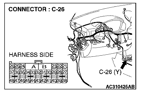
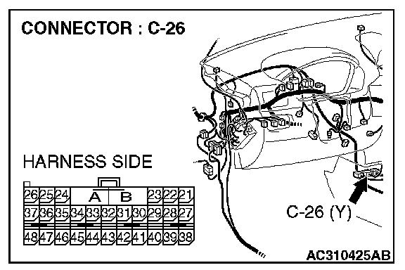
STEP 46. Check SRS-ECU connector C-26 for loose, corroded or damaged terminals, or terminals pushed back in the connector.
CAUTION: The strand end of the twist wire should be within 10 cm (4 inches) from the connector. For details refer to Service Precautions/Vehicle Damage Warnings.
Q: Is SRS-ECU connector C-26 in good condition?
YES: Go to Step 47.
NO: Repair the damaged parts.
STEP 47. Check the CAN_L line (communication line only) between joint connector (4) and SRS-ECU connector for short to ground. Measure the resistance at joint connector (4) C-101.
CAUTION: A digital multimeter should be used. For details refer to Service Precautions/Vehicle Damage Warnings.
CAUTION: The test wiring harness should be used. For details refer to Service Precautions/Vehicle Damage Warnings.
1. Disconnect joint connector (4) C-101 and SRS-ECU connector C-26, and measure the resistance at the wiring harness side of joint connector (4) C-101.
2. Turn the ignition switch to the "LOCK" (OFF) position.
CAUTION: Disconnect the negative battery terminal. For details refer to Service Precautions/Vehicle Damage Warnings.
3. Disconnect the negative battery terminal.
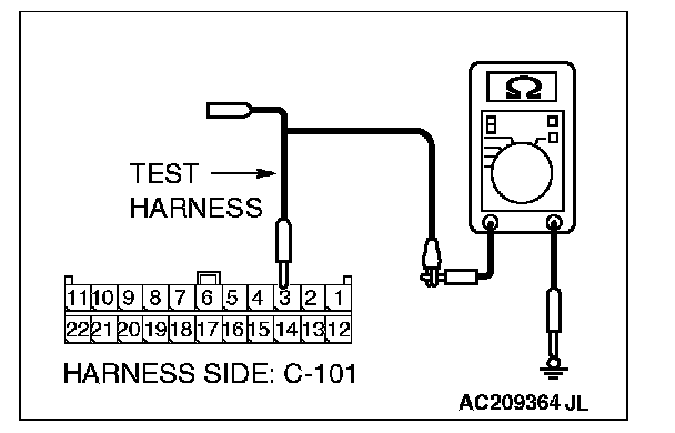
4. Measure the resistance between joint connector (4) terminal 3 and body ground.
OK: 1 kOhms or more
CAUTION: Strictly observe the specified wiring harness repair procedure. For details refer to Precautions on How to Repair The CAN Bus Lines.
Q: Does the resistance measure 1 kOhms or more?
YES:
NO:
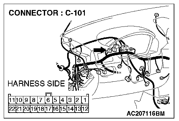
STEP 48. Check the CAN_L line (communication line including the g and yaw rate sensor) between joint connector (4) and g and yaw rate sensor connector for short to ground. Measure the resistance at joint connector (4) C-101.
CAUTION: A digital multimeter should be used. For details refer to Service Precautions/Vehicle Damage Warnings.
CAUTION: The test wiring harness should be used. For details refer to Service Precautions/Vehicle Damage Warnings.
1. Disconnect joint connector (4) C-101, and measure the resistance at the wiring harness side of joint connector (4) C-101.
2. Turn the ignition switch to the "LOCK" (OFF) position.
CAUTION: Disconnect the negative battery terminal. For details refer to Service Precautions/Vehicle Damage Warnings.
3. Disconnect the negative battery terminal.
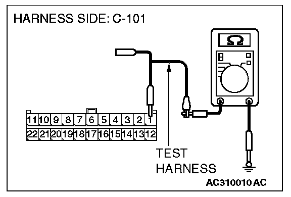
4. Measure the resistance between joint connector (4) terminal 1 and body ground.
OK: 1 kOhms or more
Q: Does the resistance measure 1 kOhms or more?
YES:
NO:
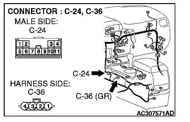
STEP 49. Check g and yaw rate sensor connector C-36 and intermediate connector C-24 for loose, corroded or damaged terminals, or terminals pushed back in the connector.
CAUTION: The strand end of the twist wire should be within 10 cm (4 inches) from the connector. For details refer to Service Precautions/Vehicle Damage Warnings.
Q: Are g and yaw rate sensor connector C-36 and intermediate connector C-24 in good condition?
YES: Go to Step 50.
NO: Repair the damaged parts.
STEP 50. Check the CAN_L line (communication line only) between intermediate connector and g and yaw rate sensor connector for short to ground. Measure the resistance at intermediate connector C-24.
CAUTION: A digital multimeter should be used. For details refer to Service Precautions/Vehicle Damage Warnings.
CAUTION: The test wiring harness should be used. For details refer to Service Precautions/Vehicle Damage Warnings.
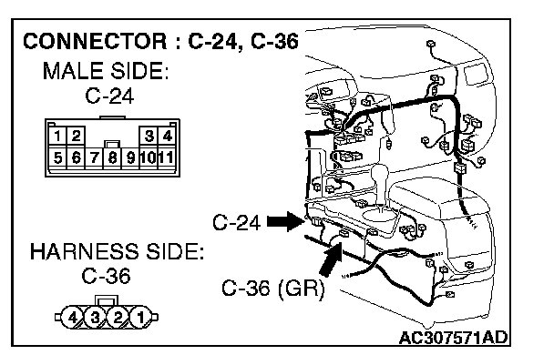
1. Disconnect intermediate connector C-24 and g and yaw rate sensor connector C-36, and measure the resistance at the wiring harness side of intermediate connector male side (at front wiring harness side).
2. Turn the ignition switch to the "LOCK" (OFF) position.
CAUTION: Disconnect the negative battery terminal. For details refer to Service Precautions/Vehicle Damage Warnings.
3. Disconnect the negative battery terminal.
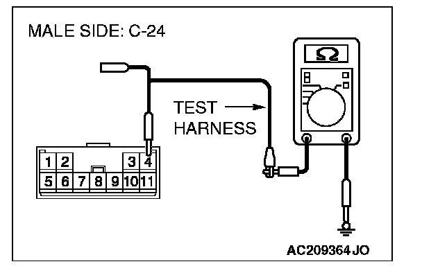
4. Measure the resistance between intermediate connector terminal 4 and body ground.
OK: 1 kOhms or more
CAUTION: Strictly observe the specified wiring harness repair procedure. For details refer to Precautions on How to Repair The CAN Bus Lines.
Q: Does the resistance measure 1 kOhms or more?
YES:
NO:
STEP 51. Check the CAN_L line (communication line only) between intermediate connector C-24 and joint connector (4) for short to ground. Measure the resistance at joint connector (4) C-101.
CAUTION: A digital multimeter should be used. For details refer to Service Precautions/Vehicle Damage Warnings.
CAUTION: The test wiring harness should be used. For details refer to Service Precautions/Vehicle Damage Warnings.
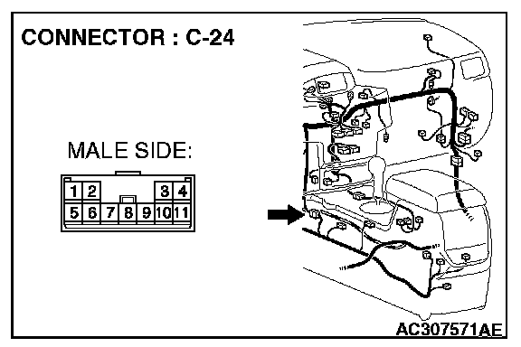

1. Disconnect intermediate connector C-24 and joint connector (4) C-101, and measure the resistance at the wiring harness side of joint connector (4) C-101.
2. Turn the ignition switch to the "LOCK" (OFF) position.
CAUTION: Disconnect the negative battery terminal. For details refer to Service Precautions/Vehicle Damage Warnings.
3. Disconnect the negative battery terminal.
4. Measure the resistance between joint connector (4) terminal 1 and body ground.
OK: 1 kOhms or more
CAUTION: Strictly observe the specified wiring harness repair procedure. For details refer to Precautions on How to Repair The CAN Bus Lines.
Q: Does the resistance measure 1 kOhms or more?
YES:
NO:
STEP 52. Check the CAN_L line (communication line including the steering wheel sensor) between joint connector (4) and steering wheel sensor connector for short to ground. Measure the resistance at joint connector (4) C-101.
CAUTION: A digital multimeter should be used. For details refer to Service Precautions/Vehicle Damage Warnings.
CAUTION: The test wiring harness should be used. For details refer to Service Precautions/Vehicle Damage Warnings.
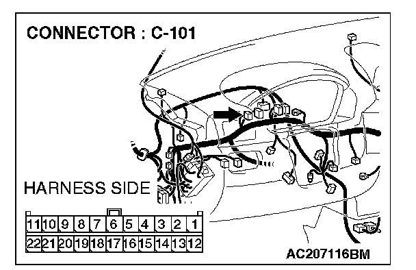
1. Disconnect joint connector (4) C-101, and measure the resistance at the wiring harness side of joint connector (4) C-101.
2. Turn the ignition switch to the "LOCK" (OFF) position.
CAUTION: Disconnect the negative battery terminal. For details refer to Service Precautions/Vehicle Damage Warnings.
3. Disconnect the negative battery terminal.
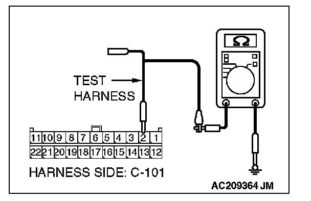
4. Measure the resistance between joint connector (4) terminal 2 and body ground.
OK: 1 kOhms or more
Q: Does the resistance measure 1 kOhms or more?
YES:
NO:
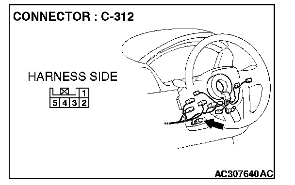
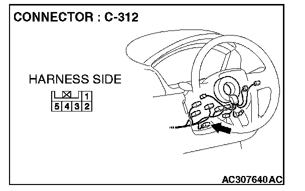
STEP 53. Check steering wheel sensor connector C-312 for loose, corroded or damaged terminals, or terminals pushed back in the connector.
CAUTION: The strand end of the twist wire should be within 10 cm (4 inches) from the connector. For details refer to Service Precautions/Vehicle Damage Warnings.
Q: Is steering wheel sensor connector C-312 in good condition?
YES: Go to Step 54.
NO: Repair the damaged parts.
STEP 54. Check the CAN_L line (communication line only) between joint connector (4) and steering wheel sensor connector for short to ground. Measure the resistance at joint connector (4) C-101.
CAUTION: A digital multimeter should be used. For details refer to Service Precautions/Vehicle Damage Warnings.
CAUTION: The test wiring harness should be used. For details refer to Service Precautions/Vehicle Damage Warnings.
1. Disconnect joint connector (4) C-101 and steering wheel sensor connector C-312, and measure the resistance at the wiring harness side of joint connector (4) C-101.
2. Turn the ignition switch to the "LOCK" (OFF) position.
CAUTION: Disconnect the negative battery terminal. For details refer to Service Precautions/Vehicle Damage Warnings.
3. Disconnect the negative battery terminal.
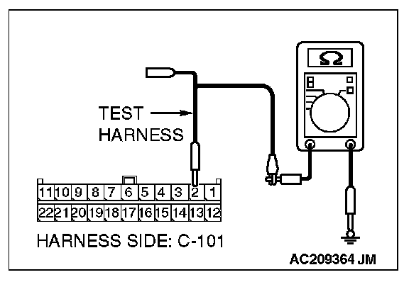
4. Measure the resistance between joint connector (4) terminal 2 and body ground.
OK: 1 kOhms or more
CAUTION: Strictly observe the specified wiring harness repair procedure. For details refer to Precautions on How to Repair The CAN Bus Lines.
Q: Does the resistance measure 1 kOhms or more?
YES:
NO:
STEP 55. Check the CAN_L line (communication line including the middle-grade multi-center display) between joint connector (4) and middle-grade multi-center display connector for short to ground. Measure the resistance at joint connector (4) C-101.
CAUTION: A digital multimeter should be used. For details refer to Service Precautions/Vehicle Damage Warnings.
CAUTION: The test wiring harness should be used. For details refer to Service Precautions/Vehicle Damage Warnings.

1. Disconnect joint connector (4) C-101, and measure the resistance at the wiring harness side of joint connector (4) C-101.
2. Turn the ignition switch to the "LOCK" (OFF) position.
CAUTION: Disconnect the negative battery terminal. For details refer to Service Precautions/Vehicle Damage Warnings.
3. Disconnect the negative battery terminal.
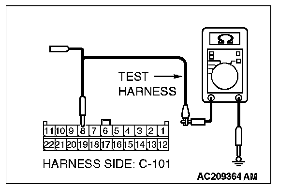
4. Measure the resistance between joint connector (4) terminal 8 and body ground.
OK: 1 kOhms or more
Q: Does the resistance measure 1 kOhms or more?
YES:
NO:

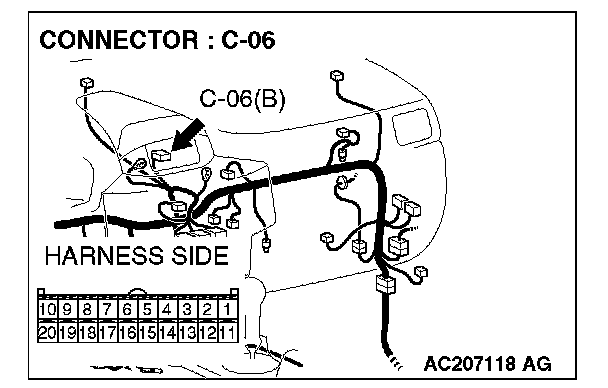
STEP 56. Check multi-center display unit (middle-grade type) connector C-06 for loose, corroded or damaged terminals, or terminals pushed back in the connector.
CAUTION: The strand end of the twist wire should be within 10 cm (4 inches) from the connector. For details refer to Service Precautions/Vehicle Damage Warnings.
Q: Is multi-center display unit (middle-grade type) connector C-06 in good condition?
YES: Go to Step 57.
NO: Repair the damaged parts.
STEP 57. Check the CAN_L line (communication line only) between joint connector (4) and multi-center display unit (middle-grade type) connector for short to ground. Measure the resistance at joint connector (4) C-101.
CAUTION: A digital multimeter should be used. For details refer to Service Precautions/Vehicle Damage Warnings.
CAUTION: The test wiring harness should be used. For details refer to Service Precautions/Vehicle Damage Warnings.

1. Disconnect joint connector (4) C-101 and multi-center display unit (middle-grade type) connector C-06, and measure the resistance at the wiring harness side of joint connector (4) C-101.
2. Turn the ignition switch to the "LOCK" (OFF) position.
CAUTION: Disconnect the negative battery terminal. For details refer to Service Precautions/Vehicle Damage Warnings.
3. Disconnect the negative battery terminal.
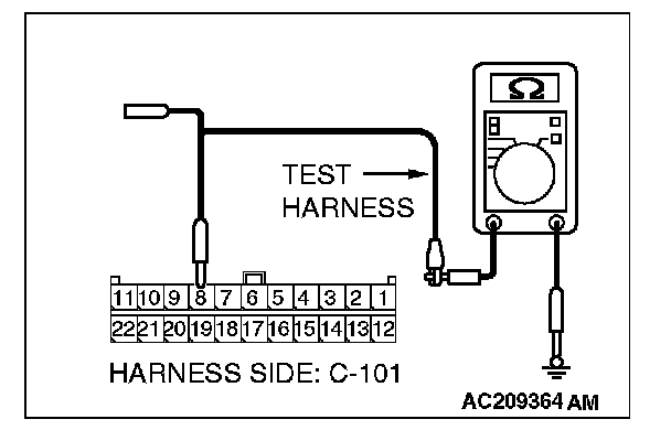
4. Measure the resistance between joint connector (4) terminal 8 and body ground.
OK: 1 kOhms or more
CAUTION: Strictly observe the specified wiring harness repair procedure. For details refer to Precautions on How to Repair The CAN Bus Lines.
Q: Does the resistance measure 1 kOhms or more?
YES:
NO:
STEP 58. Check the CAN_L line (communication line only) between joint connector (4) and the data link connector for short to ground. Measure the resistance at joint connector (4) C-101.
CAUTION: A digital multimeter should be used. For details refer to Service Precautions/Vehicle Damage Warnings.
CAUTION: The test wiring harness should be used. For details refer to Service Precautions/Vehicle Damage Warnings.

1. Disconnect joint connector (4) C-101, and measure the resistance at the wiring harness side of joint connector (4) C-101.
2. Turn the ignition switch to the "LOCK" (OFF) position.
CAUTION: Disconnect the negative battery terminal. For details refer to Service Precautions/Vehicle Damage Warnings.
3. Disconnect the negative battery terminal.
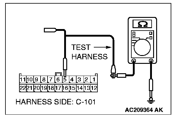
4. Measure the resistance between joint connector (4) terminal 5 and body ground.
OK: 1 kOhms or more
CAUTION: Strictly observe the specified wiring harness repair procedure. For details refer to Precautions on How to Repair The CAN Bus Lines.
Q: Does the resistance measure 1 kOhms or more?
YES:
NO:
STEP 59. Check the CAN_L line (communication line only) between intermediate connector C-31 and joint connector (4) for short to ground. Measure the resistance at joint connector (4) C-101.
CAUTION: A digital multimeter should be used. For details refer to Service Precautions/Vehicle Damage Warnings.
CAUTION: The test wiring harness should be used. For details refer to Service Precautions/Vehicle Damage Warnings.
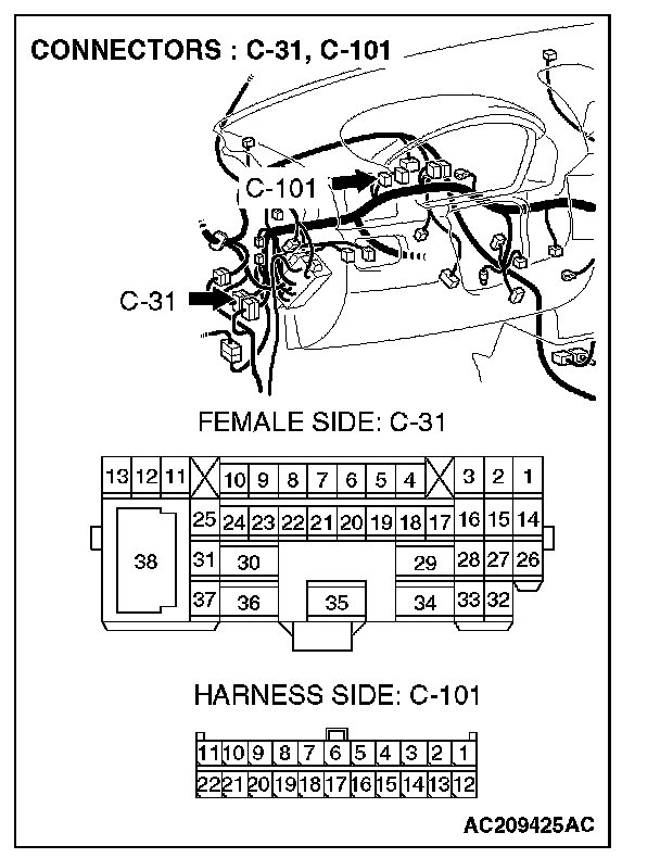
1. Disconnect intermediate connector C-31 and joint connector (4) C-101, and measure the resistance at the wiring harness side of joint connector (4) C-101.
2. Turn the ignition switch to the "LOCK" (OFF) position.
CAUTION: Disconnect the negative battery terminal. For details refer to Service Precautions/Vehicle Damage Warnings.
3. Disconnect the negative battery terminal.
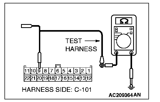
4. Measure the resistance between joint connector (4) terminal 9 and body ground.
OK: 1 kOhms or more
CAUTION: Strictly observe the specified wiring harness repair procedure. For details refer to Precautions on How to Repair The CAN Bus Lines.
Q: Does the resistance measure 1 kOhms or more?
YES:
NO:
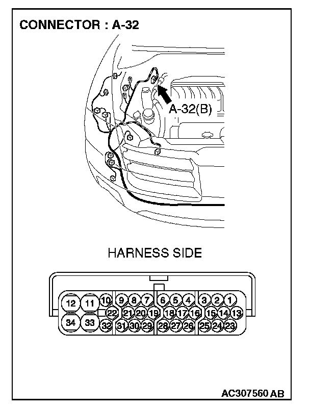
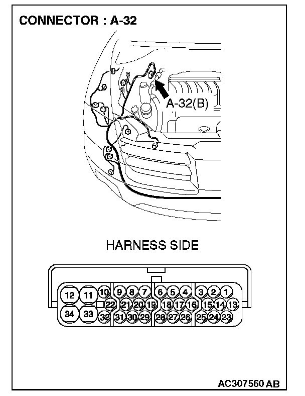
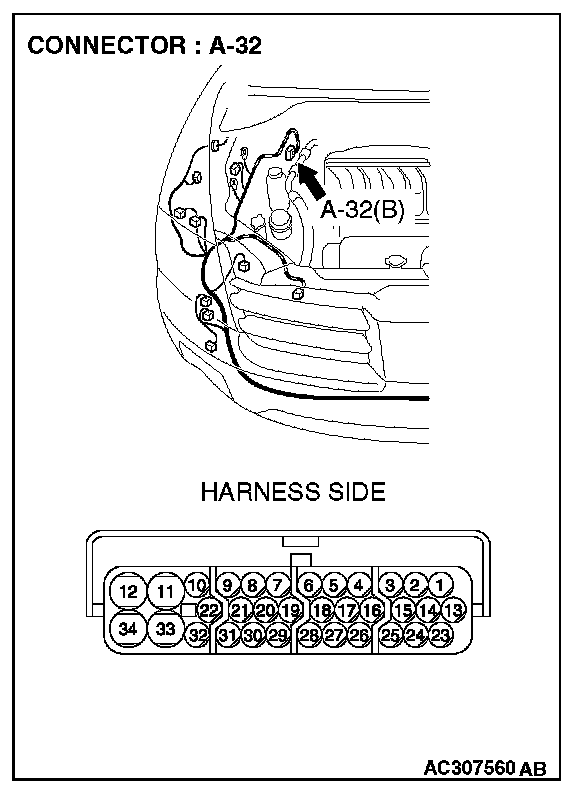
STEP 60. Check ASC/TCL-ECU connector A-32 for loose, corroded or damaged terminals, or terminals pushed back in the connector.
CAUTION: The strand end of the twist wire should be within 10 cm (4 inches) from the connector. For details refer to Service Precautions/Vehicle Damage Warnings.
Q: Is ASC/TCL-ECU connector A-32 in good condition?
YES: Go to Step 61.
NO: Repair the damaged parts.
STEP 61.Check the CAN_L line (communication line only) between intermediate connector C-31 and ASC/TCL-ECU connector for short to ground. Measure the resistance at intermediate connector C-31.
CAUTION: A digital multimeter should be used. For details refer to Service Precautions/Vehicle Damage Warnings.
CAUTION: The test wiring harness should be used. For details refer to Service Precautions/Vehicle Damage Warnings.
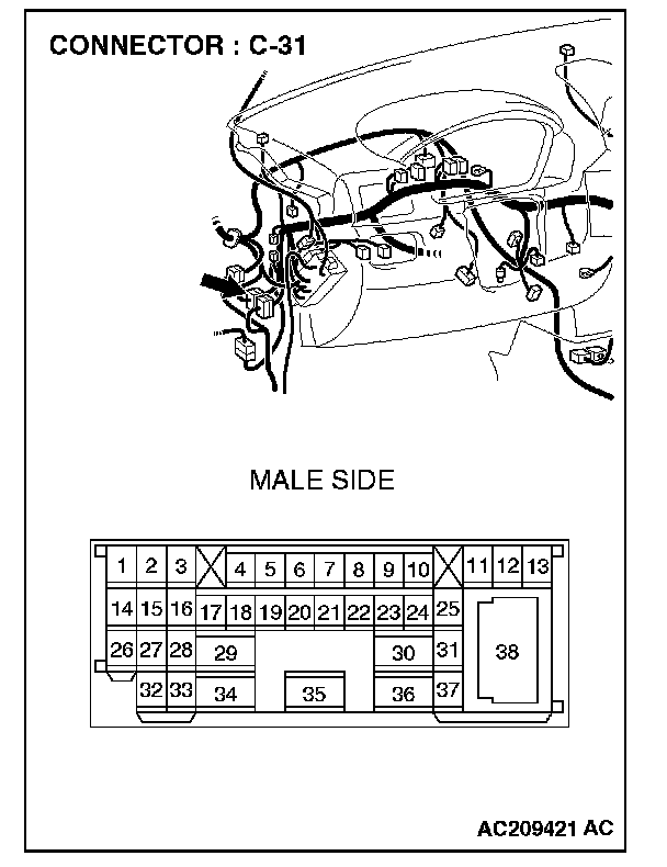
1. Disconnect intermediate connector C-31 and ASC/TCL-ECU connector A-32, and measure the resistance at the male side of intermediate connector C-31 (at front wiring harness side).
2. Turn the ignition switch to the "LOCK" (OFF) position.
CAUTION: Disconnect the negative battery terminal. For details refer to Service Precautions/Vehicle Damage Warnings.
3. Disconnect the negative battery terminal.
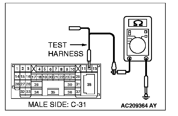
4. Measure the resistance between intermediate connector C-31 terminal 12 and body ground.
OK: 1 kOhms or more
CAUTION: Strictly observe the specified wiring harness repair procedure. For details refer to Precautions on How to Repair The CAN Bus Lines.
Q: Does the resistance measure 1 kOhms or more?
YES:
NO:
STEP 62.Check the CAN_L line (communication line only) between the powertrain control module connector and ASC/TCL-ECU connector for short to ground. Measure the resistance at powertrain control module connector B-18.
CAUTION: A digital multimeter should be used. For details refer to Service Precautions/Vehicle Damage Warnings.
CAUTION: The test wiring harness should be used. For details refer to Service Precautions/Vehicle Damage Warnings.
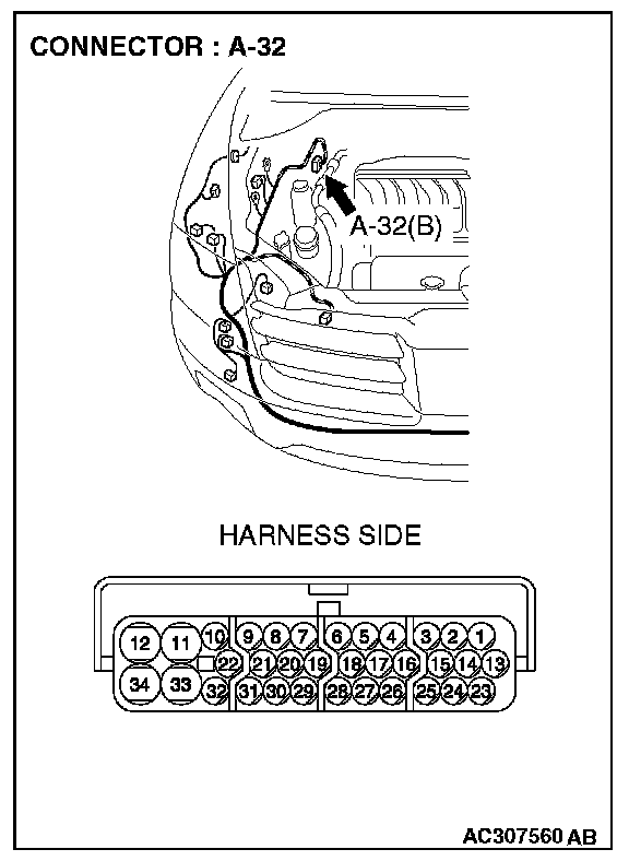
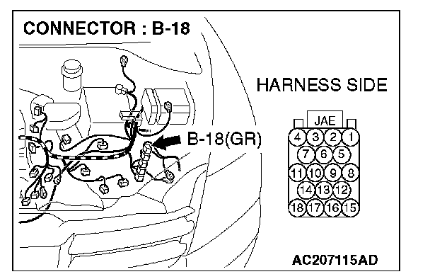
1. Disconnect powertrain control module connector B-18 and ASC/TCL-ECU connector A-32, and measure the resistance at the harness side of powertrain control module connector B-18.
2. Turn the ignition switch to the "LOCK" (OFF) position.
CAUTION: Disconnect the negative battery terminal. For details refer to Service Precautions/Vehicle Damage Warnings.
3. Disconnect the negative battery terminal.
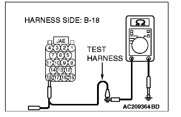
4. Measure the resistance between powertrain control module connector terminal 18 and body ground.
OK: 1 kOhms or more
CAUTION: Strictly observe the specified wiring harness repair procedure. For details refer to Precautions on How to Repair The CAN Bus Lines.
Q: Does the resistance measure 1 kOhms or more?
YES:
NO:
STEP 63. Check the CAN_L line inside the ASC/TCL-ECU for short to ground. Measure the resistance at ASC/TCL-ECU connector A-32.
CAUTION: A digital multimeter should be used. For details refer to Service Precautions/Vehicle Damage Warnings.
CAUTION: The test wiring harness should be used. For details refer to Service Precautions/Vehicle Damage Warnings.
1. Disconnect ASC/TCL-ECU connector A-32.
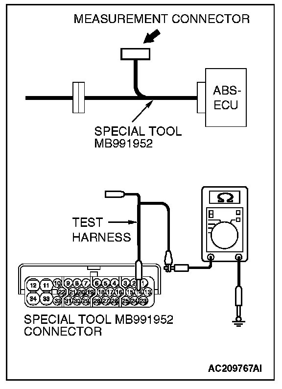
2. Connect special tool MB991952 (ABS check harness) to the ASC/TCL-ECU and the wiring harness, and measure the resistance at special tool MB991952 (ABS check harness).
3. Turn the ignition switch to the "LOCK" (OFF) position.
CAUTION: Disconnect the negative battery terminal. For details refer to Service Precautions/Vehicle Damage Warnings.
4. Disconnect the negative battery terminal.
5. Measure the resistance between special tool MB991952 (ABS check harness) connector terminal 14 and body ground.
OK: 1 kOhms or more
Q: Does the resistance measure 1 kOhms or more?
YES:
NO: