Starter Motor: Testing and Inspection
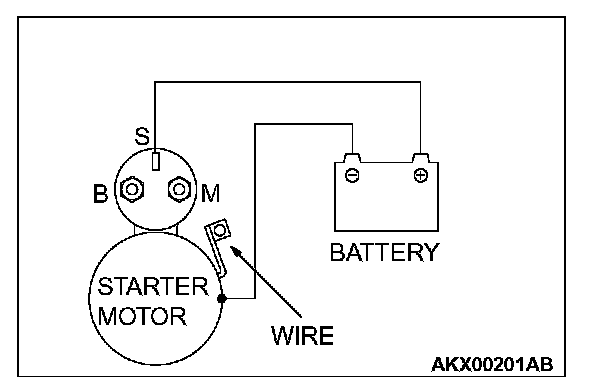
INSPECTIONPINION GAP ADJUSTMENT
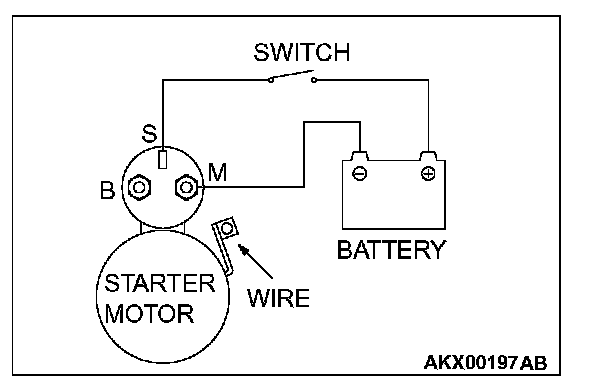
1. Disconnect the field coil wire from the M-terminal of the magnetic switch.
2. Connect a 12-volt battery between the S-terminal and M-terminal.
CAUTION: This test must be performed quickly (in less than 10 seconds) to prevent the coil from burning.
3. Set the switch to "ON", and the pinion will move out.
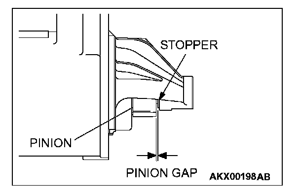
4. Check the pinion-to-stopper clearance (pinion gap) with a feeler gauge.
Standard value: 0.5 - 2.0 mm (0.02 - 0.07 inch)
5. If the pinion gap is out of specification, adjust by adding or removing gasket(s) between the magnetic switch and front bracket.
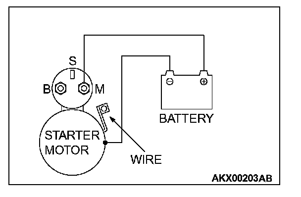
MAGNETIC SWITCH PULL-IN TEST
1. Disconnect the field coil wire from the M-terminal of the magnetic switch.
CAUTION: This test must be performed quickly (in less than 10 seconds) to prevent the coil from burning.
2. Connect a 12-volt battery between the S-terminal and M-terminal.
3. If the pinion moves out, the pull-in coil is good. If it doesn't, replace the magnetic switch.
MAGNETIC SWITCH HOLD-IN TEST
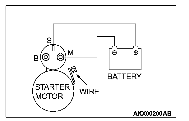
1. Disconnect the field coil wire from the M-terminal of the magnetic switch.
CAUTION: This test must be performed quickly (in less than 10 seconds) to prevent the coil from burning.
2. Connect a 12-volt battery between the S-terminal and body.
3. Manually pull out the pinion as far as the pinion stopper position.
4. If the pinion remains out, everything is operating properly. If the pinion moves in, the hold-in circuit is open. Replace the magnetic switch.
FREE RUNNING TEST
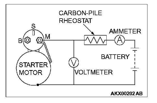
1. Place the starter motor in a vise equipped with soft jaws and connect a fully-charged 12-volt battery to the starter motor as follows:
2. Connect a test ammeter (100-ampere scale) and carbon pile rheostat in series between the positive battery terminal and starter motor terminal.
3. Connect a voltmeter (15-volt scale) across the starter motor.
4. Rotate carbon pile to full-resistance position.
5. Connect the battery cable from the negative battery terminal to the starter motor body.
6. Adjust the rheostat until the battery positive voltage shown by the voltmeter is 11 V.
7. Confirm that the maximum amperage is within the specifications and that the starter motor turns smoothly and freely.
Current: maximum 90 Amps
MAGNETIC SWITCH RETURN TEST
1. Disconnect the field coil wire from the M-terminal of the magnetic switch.
CAUTION: This test must be performed quickly (in less than 10 seconds) to prevent the coil from burning.
2. Connect a 12-volt battery between the M-terminal and body.
WARNING: Be careful not to get your fingers caught when pulling out the pinion.
3. Pull the pinion out and release. If the pinion quickly returns to its original position, everything is operating properly. If it doesn't, replace the magnetic switch.
INSPECTION
COMMUTATOR CHECK
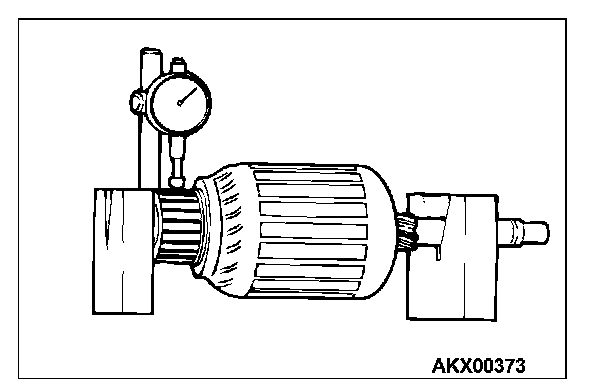
1. Place the armature on a pair of V-blocks, and check the deflection by using a dial gauge.
Standard value: 0.05 mm (0.002 inch)
Limit: 0.1 mm (0.004 inch)
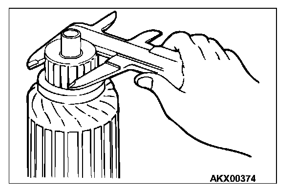
2. Check the outer diameter of the commutator.
Standard value: 29.4 mm (1.16 inches)
Minimum limit: 28.8 mm (1.13 inches)
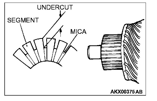
3. Check the depth of the undercut between segments.
Standard value: 0.5 mm (0.02 inch)
Minimum limit: 0.2 mm (0.008 inch)
BRUSH CHECK
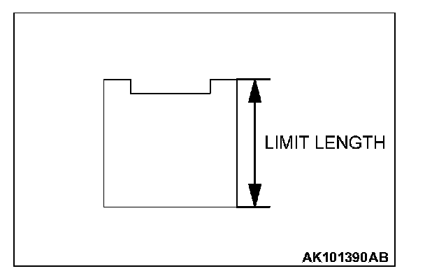
1. Check the brush for roughness of the surface that contacts the commutator and check the brush length.Replace the brush holder if this measurement exceeds the limit.
Minimum limit: 7.0 mm (0.28 inch)
2. In the case contacting surface has been corrected or the brush has been replaced, correct the contacting surface by winding sandpaper around the commutator.
OVERRUNNING CLUTCH CHECK
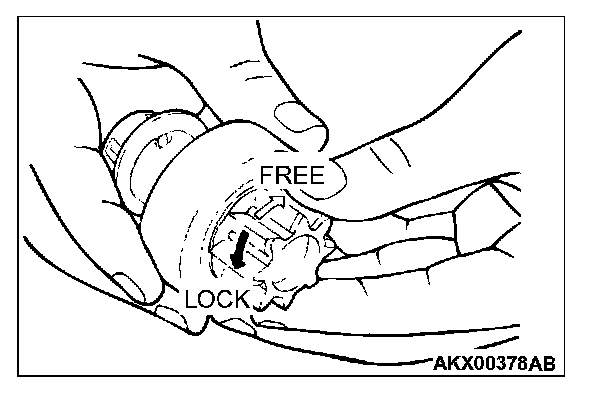
1. While holding the clutch housing, rotate the pinion. The drive pinion should rotate smoothly in one direction, but should not rotate in opposite direction. If the clutch does not function properly, replace the overrunning clutch assembly.
2. Inspect the pinion for wear or burrs. If the pinion is worn or burred, replace the overrunning clutch assembly. If the pinion is damaged, also inspect the ring gear for wear or burrs.
FRONT AND REAR BRACKET BUSHING CHECK
Inspect the bushing for wear or burrs. If the bushing is worn or burred, replace the front bracket assembly or rear bracket assembly.
ARMATURE CHECK
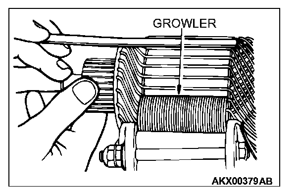
1. Check that the armature coil is not grounded.
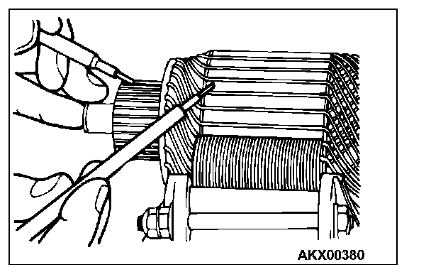
2. Place the armature in a growler.
3. Hold a thin steel blade parallel and just above while rotating the armature slowly in the growler. A shorted armature will cause a blade to vibrate and be attracted to the core. Replace the shorted armature.
4. Check the insulation between the armature coil cores and the commutator segments. They are normal if there is no continuity.
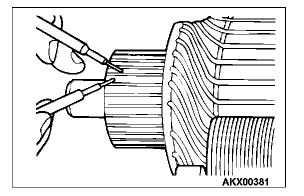
5. Check for continuity between the segments. The condition is normal if there is continuity.
MAGNETIC SWITCH
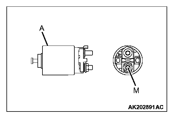
1. Coil open circuit test
- Check that there is continuity between the M terminal and body A.
- If there is no continuity, replace the magnetic switch.
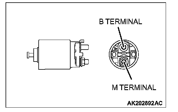
2. Contact fusion check
- Check that there is no continuity between the B terminal and M terminal.
- If there is continuity, replace the magnetic switch.
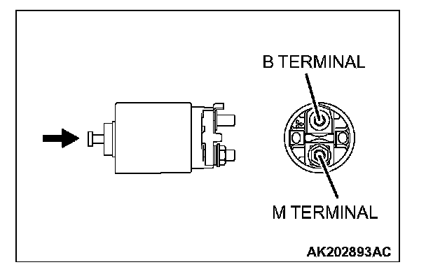
3. Switch contact check
- Push the indicated end of the magnetic switch with a strong force to close the internal contacts. Without releasing the switch end, check that there is continuity between the B terminal and M terminal.
- If there is no continuity, replace the magnetic switch.