Vehicle - New Model Technical Service Information
No.: TSB-05-00-011DATE: September, 2005
MODEL: 2006 Raider
SUBJECT:
RAIDER NEW MODEL
TECHNICAL SERVICE INFORMATION
PURPOSE
This bulletin contains important new model service information for 2006 Mitsubishi Raider.
The 2006 Raider Service Manual CD (p/n MSCD-003B-2006) includes the Body Repair Manual. The CD is provided with this TSB mailing to dealers.
^ Refer to TSB-05-00-010 for Raider PDI instructions.
^ Refer to TSB-05-00-012 for Raider towing specifications and camper usage recommendations.
^ Refer to TSB-05-00-013 for instructions on using the MUT-III scan tool on Raider vehicles.
^ Refer to Warranty Bulletin WB 2006-005 and the "Labor Operation Time Schedule and Special Raider Policies and Procedures for 2006 Raider" booklet for warranty claim and audio exchange information.
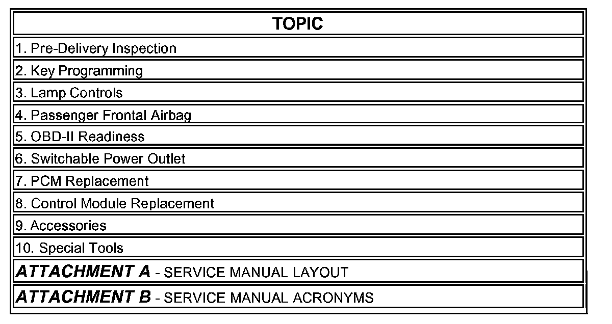
1. PRE-DELIVERY INSPECTION
Dealers must use a separate "Truck Pre-Delivery Inspection Worksheet" for Raider (part number MSSF1O5NMO6). A small quantity was sent to all dealers. Order additional copies from Relizon. Refer to TSB-05-00-O10 for details on Raider PDI procedures.
2. KEY PROGRAMMING
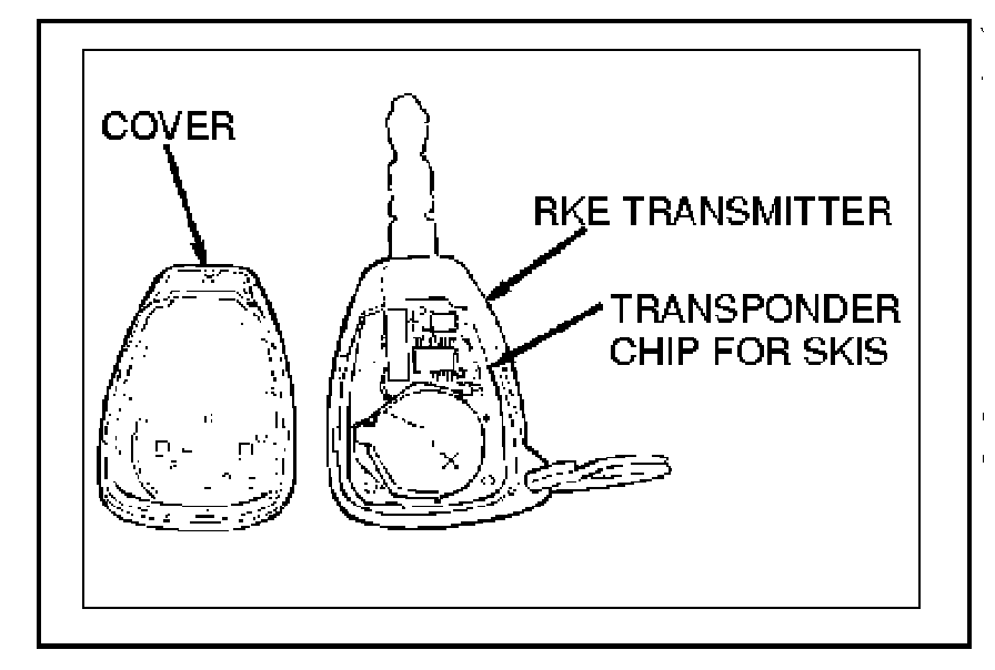
Vehicle keys contain the transmitter for the Remote Keyless Entry System (RKE) and the Sentry Key Immobilizer System (SKIS).
Most 2006 Raiders have RKE only. SKIS is available as a factory-installed option only on XLS-V8 models. Models equipped with SKIS can be identified by the illumination of the security indicator in the instrument cluster, which illuminates briefly as a bulb test after the ignition switch is turned ON.
The Sentry Key Remote Entry Module (SKREEM) is also sometimes referred to in the service manual as the Wireless Control Module (WCM). Two SKREEM modules are available: one for vehicles with RKE only; and one for vehicles equipped with RKE and SKIS. The SKREEM and its antenna are concealed under the steering column shrouds.
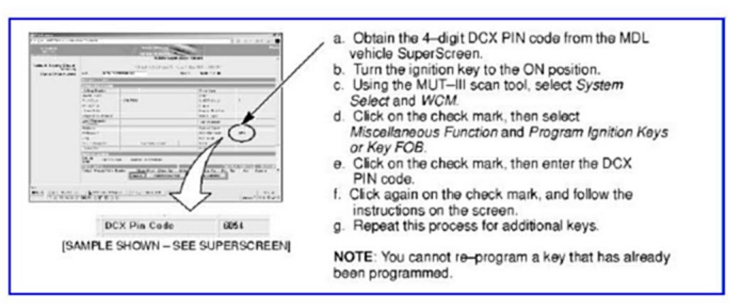
You can program up to eight keys (transmitters). To program or add a new key with the MUT-III:
CAUTION
DO NOT ERASE THE PROGRAMMING ON A SENTRY KEY THAT WILL BE RE-USED. AFTER A SENTRY KEY IS ERASED, IT CANNOT BE REPROGRAMMED.
If two valid (already programmed) keys are available, the customer or dealership can program additional keys without the scan tool as follows:
a. Insert the first valid key into the ignition and turn the ignition to the ON position for at least 3 seconds but no longer than 15 seconds. Turn the ignition back to the OFF position and remove the first key.
b. Insert the second valid key and turn the ignition to the ON position within 15 seconds. After 10 seconds, a chime will sound and the "Security" light will flash. Turn the ignition back to the OFF position and remove the key.
c. Within 1 minute of removing the second key, insert a blank key into the ignition and turn the ignition to the ON position. Wait 10 seconds. A single chime will sound. The "Security" light will stop flashing and come on for 3 seconds. The new key is now programmed. Repeat this process for additional keys.
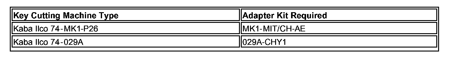
To cut keys for Raider vehicles, key cutting machines (except Ultracode machines) require a special adapter kit, which are available from SPX (1-888-727-6672):
If your dealership has a different key cutting machine, contact the manufacturer's representative.
Key blanks are available from your facing PDC:
p/n 05174497AA - Raider models without RKE/immobilizer
p/n 05170630AA - Raider models with RKE without immobilizer
p/n 05170631AA - Raider models with both RKE and immobilizer
3. LAMP CONTROLS
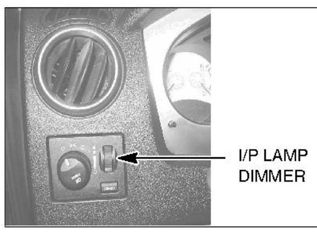
a. For daytime driving with the headlamps on, advise customers to turn the instrument panel lamp dimming rheostat to the fully up position. This position will keep the audio display at full brightness to improve daytime visibility while the headlamps are on. If the rheostat is not in this position, the audio display may be difficult to read when the headlamps are on during the daytime.
With the dimmer switch in the fully up position, the dome light will stay on after the doors are closed. With the dimmer switch in the fully down position, the dome light will not come on.
b. The headlamps have a "Delayed Off" feature to help illuminate your way after exiting the vehicle. The delay works as follows: With the headlamps on, turn the ignition off, remove the keys, and turn the headlamp switch to the off position and exit the vehicle. The lights will stay on for about 60 seconds.
4. PASSENGER FRONTAL AIRBAG
Refer to the Section 2 in the Raider owner's manual for details on operation of the Occupant Classification System.
On Extended Cab models, the passenger frontal airbag can be manually shut off and on as follows:
To turn off the passenger frontal airbag: Insert the ignition key in the Passenger Airbag On/Off switch. Push the key in and turn clockwise. Then remove the key. The passenger airbag disable lamp will display "OFF" when the ignition switch is turned on.
To turn on the passenger frontal airbag: Insert the ignition key in the Passenger Airbag On/Off switch. Push the key in and turn counterclockwise. Then remove the key. The passenger airbag disable lamp will display "ON" when the ignition switch is turned on.
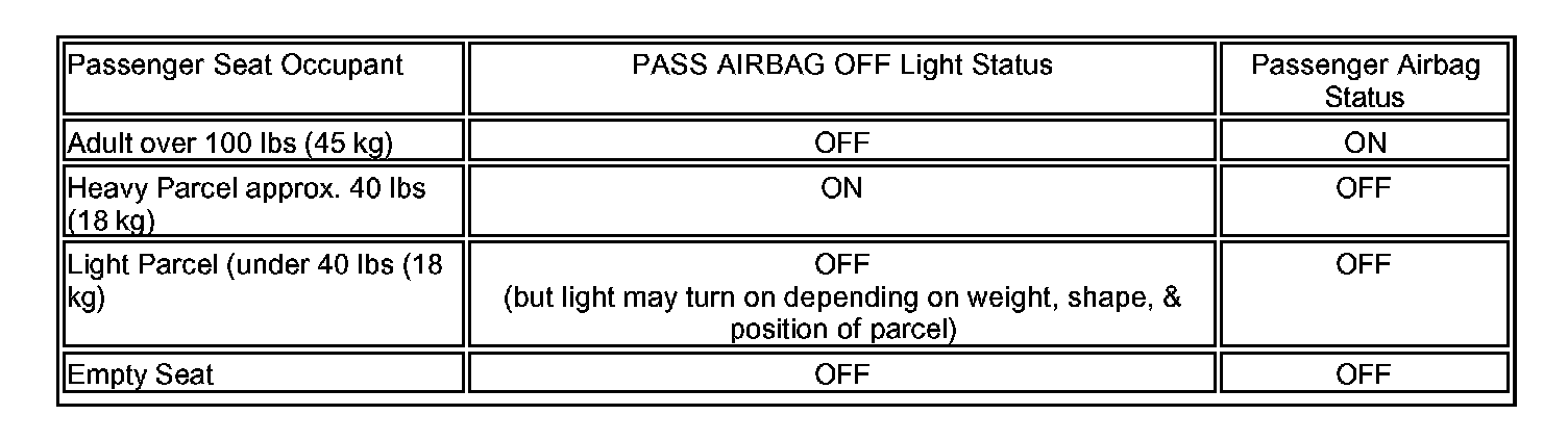
Operation of passenger frontal airbag light:
5. OBD-II READINESS

The "Malfunction Indicator Light" (Check Engine light) is part of an onboard diagnostic system that monitors the emissions and engine control system.
^ If the vehicle is ready for OBD-II emissions testing, this light will come on when the ignition is first turned on, and remain on (as a bulb check) until the engine is started.
^ If the vehicle is NOT ready for OBD-II emissions testing, this light will come on for 15 seconds, then blink for 5 seconds, and remain on until the vehicle is started. Drive the OBD-II drive cycle for each monitor. Refer to Group 17 in the service manual for details on OBD-II drive cycles.
6. SWITCHABLE POWER OUTLET
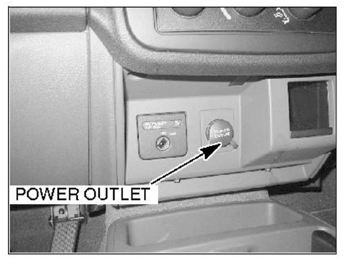
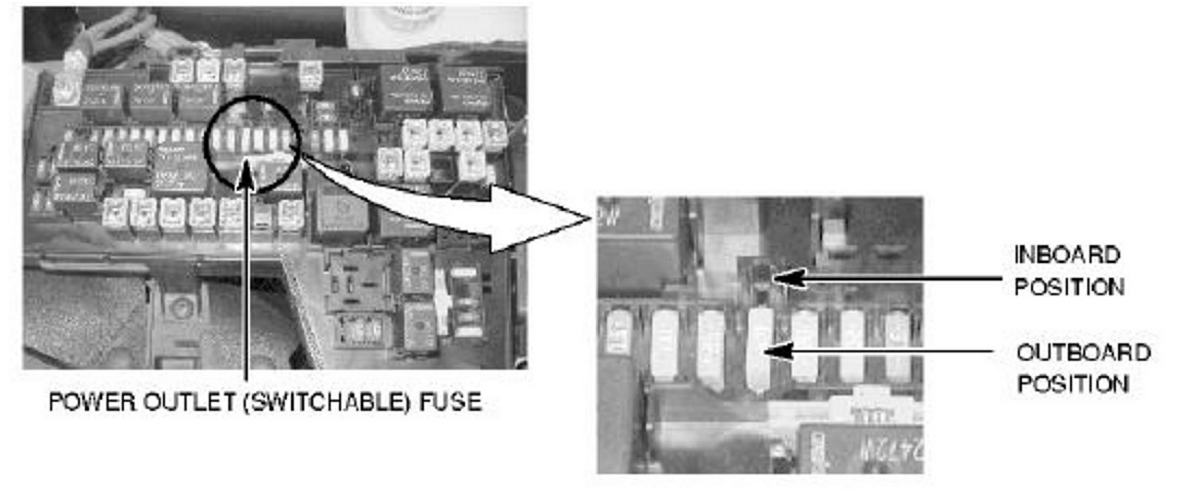
The power outlet in the instrument panel can be configured to operate only when the ignition is ON, or when the ignition is ON or OFF (battery feed). (The owner's manual for early production vehicles incorrectly identifies the switchable outlet as the console power outlet.)
Locate the power outlet (switchable) fuse in the fusebox in the engine compartment. Refer to the fuse diagram provided on the underside of the fusebox lid.
The power outlet in the instrument panel will operate by battery feed (ignition in ON or OFF position) when the power outlet (switchable) fuse is in the inboard position as shown. When this fuse is in the outboard position, the outlet will operate only with the ignition ON.
7. PCM REPLACEMENT
Replacement PCMs for Raiders require programming. Until it is programmed, the PGM will not operate, and a "Not Programmed" DTC will be set. Refer to TSB-05-00-013 for details.
CAUTION
NEVER install a programmed PCM from one Raider into another Raider. Damage will result.
8. CONTROL MODULE REPLACEMENT
a CCN: When the Cabin Control Node (contained in the instrument cluster) requires replacement, dealers must contact Radio Sales and Service Corporation (RSSG) on-line. RSSG is the authorized Mitsubishi service center and supplier for Raider instrument cluster exchange units. Refer to page 12 of the "Labor Operation Time Schedule and Special Raider Policies and Procedures for 2006 Raider" booklet for details on opening an account with RSSG. These booklets were shipped to dealers in early September.
DO NOT REPLACE FAILED INSTRUMENT CLUSTERS WITH NEW ONES FROM DEALER STOCK. When a dealer orders an exchange instrument cluster from RSSG, the VIN and mileage must be entered in the on-line order. RSSG will set the replacement odometer's mileage to match the mileage reading of the failed unit before sending it to the dealer.
b. Certain control modules listed below must not be replaced at the same time. An irreversible fault will be set in both modules.
CAUTION
^ Do not replace the Occupant Restraint Controller (ORG) and Occupant Classification Module (0CM) at the same time. If both must be replaced, replace one module, then run the Supplemental Restraints Verification Test with the MUT-III before replacing the other module.
^ Do not replace the Front Control Module (FCM) and Cabin Control Node (CCN) at the same time. If both require replacement, you must first contact Tech Line for parts ordering authorization.
^ If you replace the Wireless Control Module (WCM) and the PCM at the same time, you must perform the following functions in this order. (Refer to TSB-05-00-013 for MUT-III instructions.)
(1) Program the new blank PCM.
(2) Manually input the VIN to the new PCM.
(3) Perform "WCM Replaced" initialization (in the MUT-III System Select menu, select WCM, then Misc. Function, then WCM Replaced).
(4) Program new Sentry keys.
(5) Perform the "PCM Replacement" function (in the MUT-III System Select menu, select WCM, Misc. Function, then PCM Replaced).
9. RAIDER ACCESSORIES
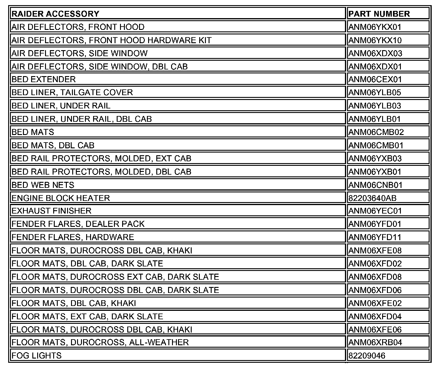
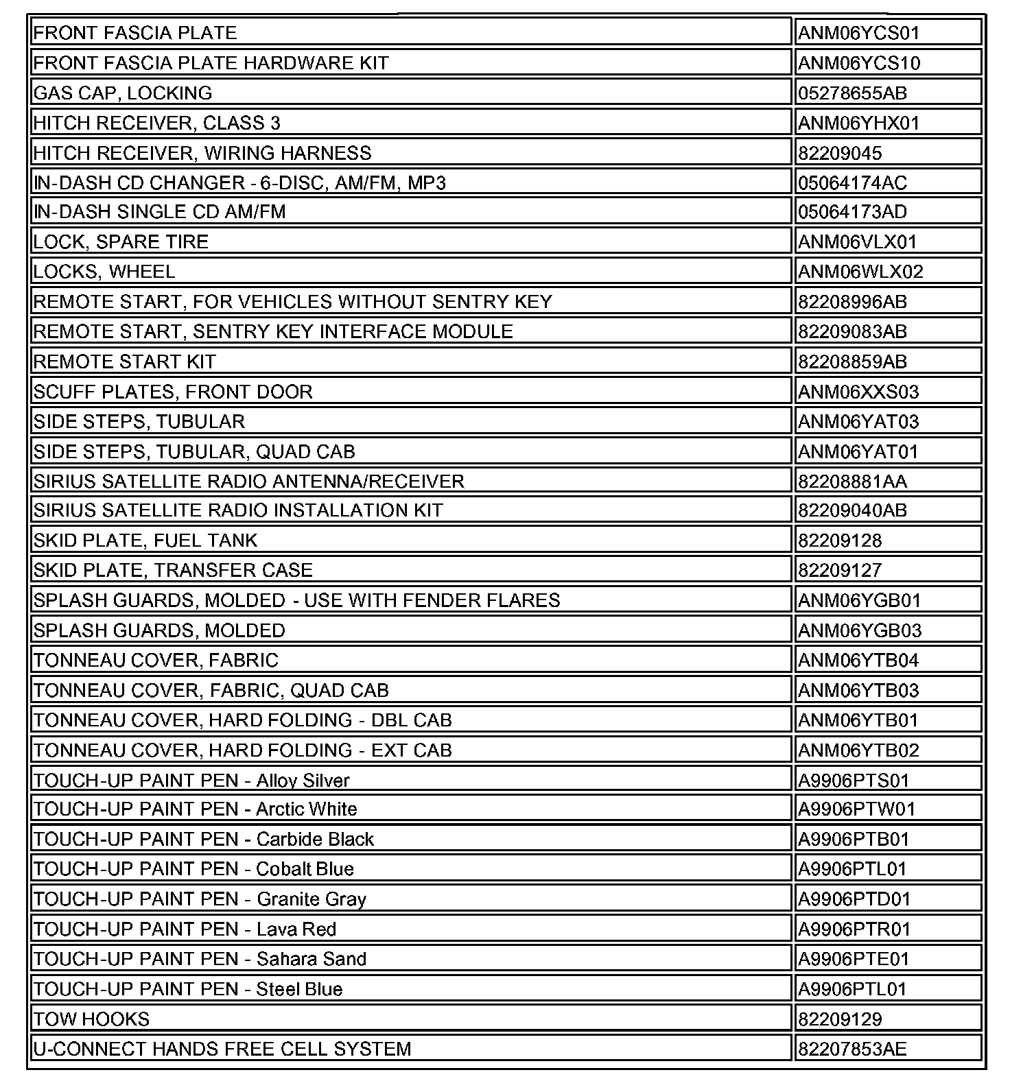
Installation instructions are included with each accessory.
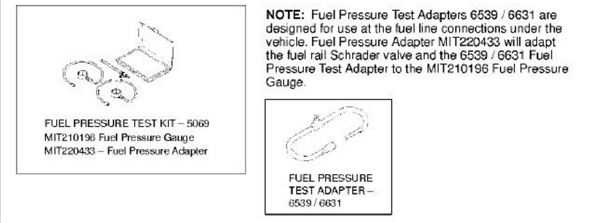
10. SPECIAL TOOLS
The 2006 Raider Essential Tool Kit, containing 128 tools, was shipped to dealers in August. A flier included with the kit lists the tools and their usage. A tool cabinet for storing these tools was also shipped in August. Tool cabinet labels and locators are provided with the tool kit. Three additional tools for Raider will be sent to dealers in the near future.
If your dealership did not receive the Raider Essential Tool Kit or storage cabinet, or if you require additional tools mentioned in the Raider service manual, please contact SPX.
Raider Service Manual tool designations are 4-digit Daimler-Chrysler tool numbers. To place orders for Raider tools, use the Mitsubishi tool number, if provided.
ATTACHMENT A - RAIDER SERVICE MANUAL LAYOUT
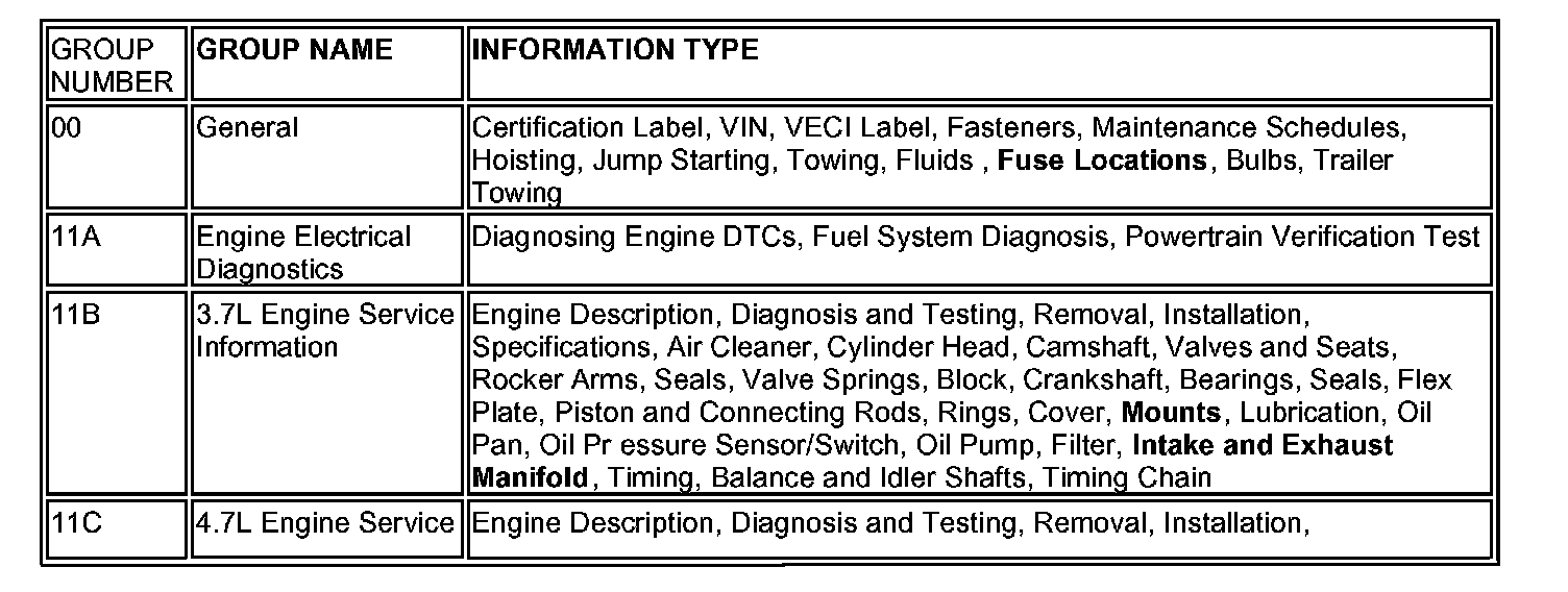
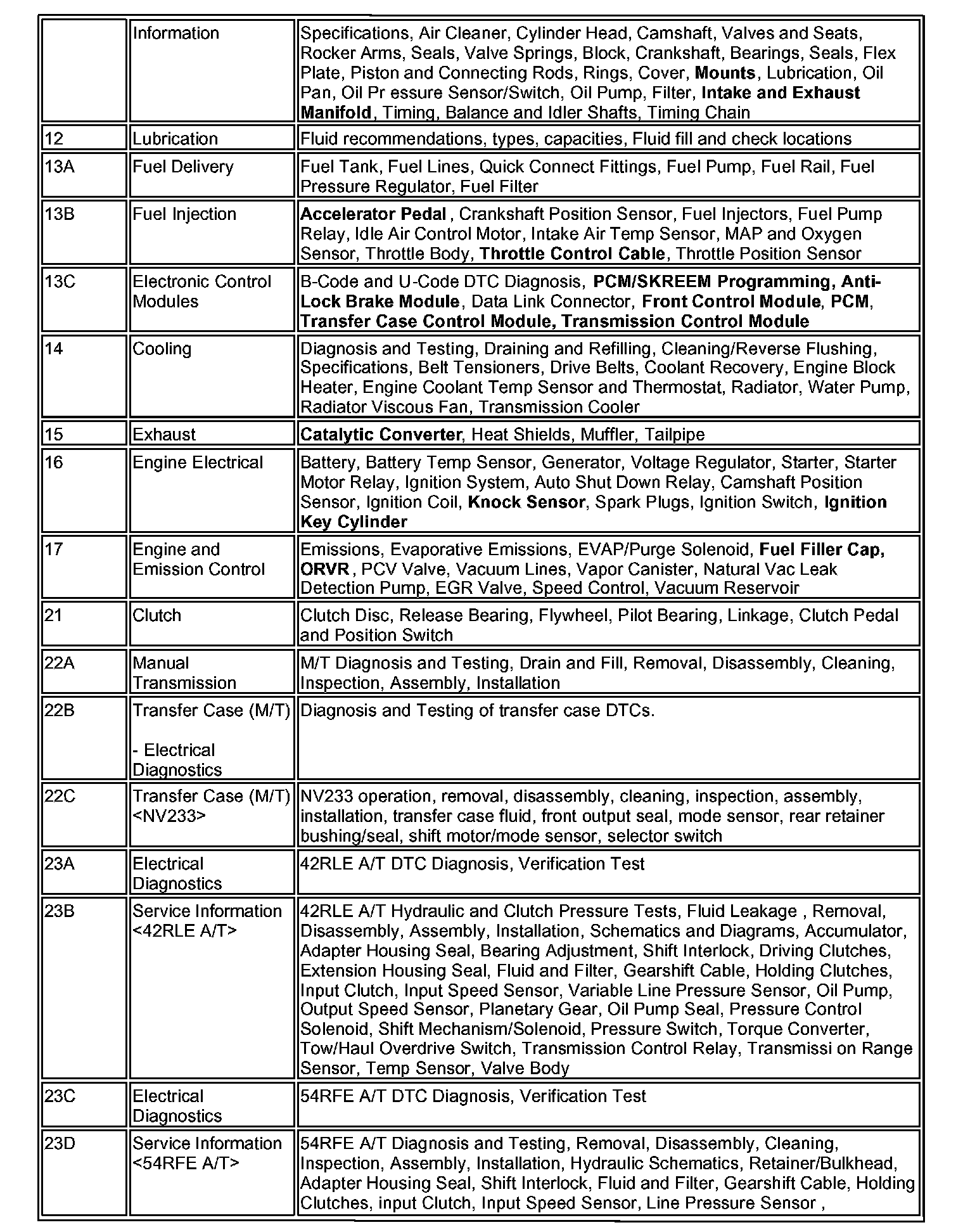
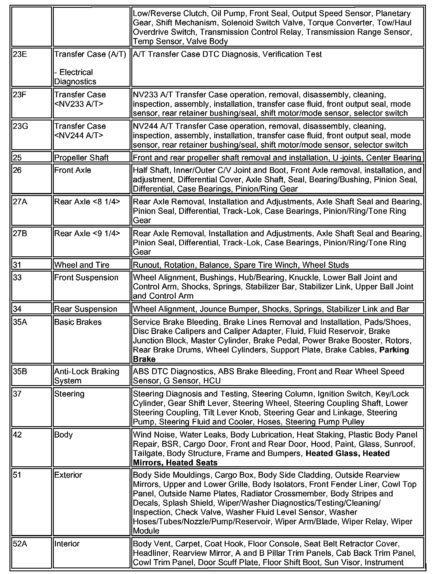
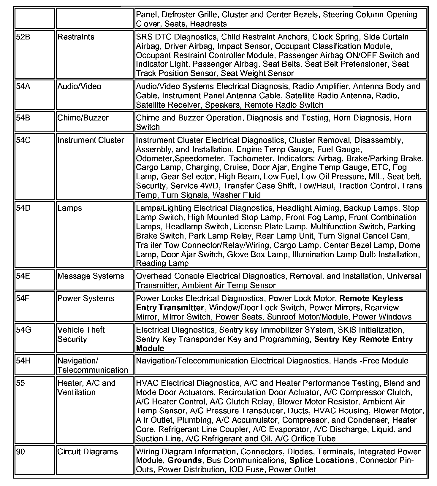
The Raider service manual layout is similar to other Mitsubishi manuals. However, some information (highlighted in bold text in the chart) is located in different areas of the manual than you may be accustomed to.
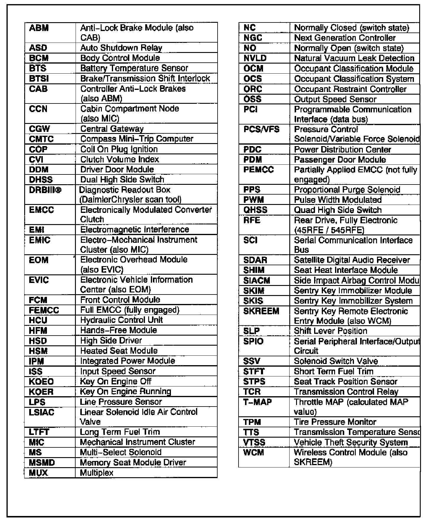
ATTACHMENT B - RAIDER SERVICE MANUAL ACRONYMS