Part 2
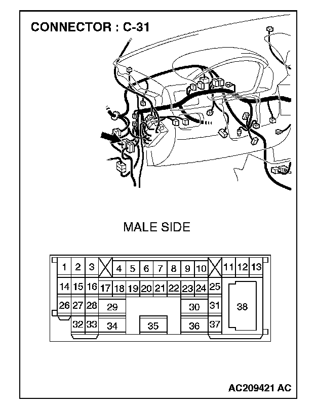
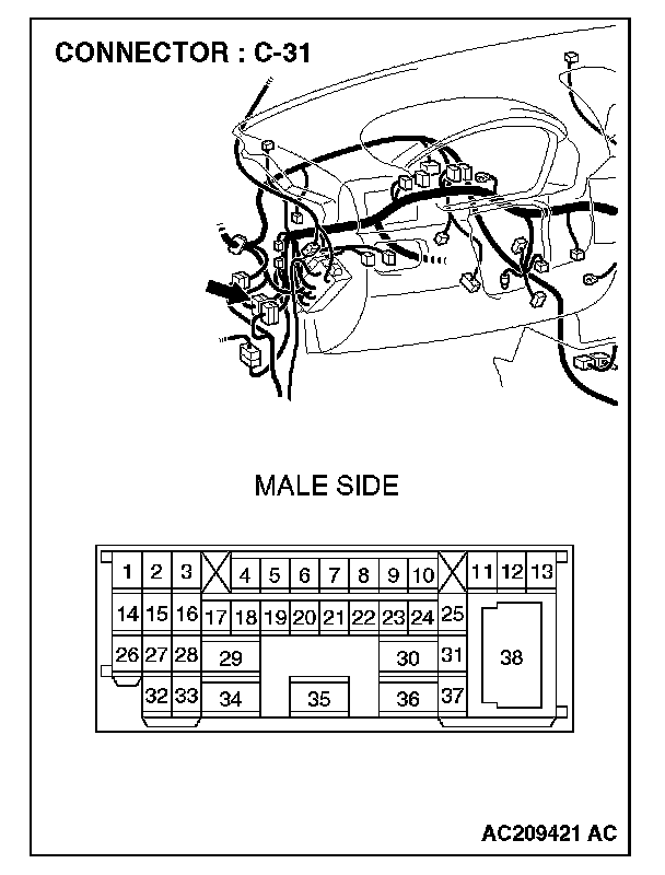
STEP 27. Check intermediate connector C-31 for loose, corroded or damaged terminals, or terminals pushed back in the connector.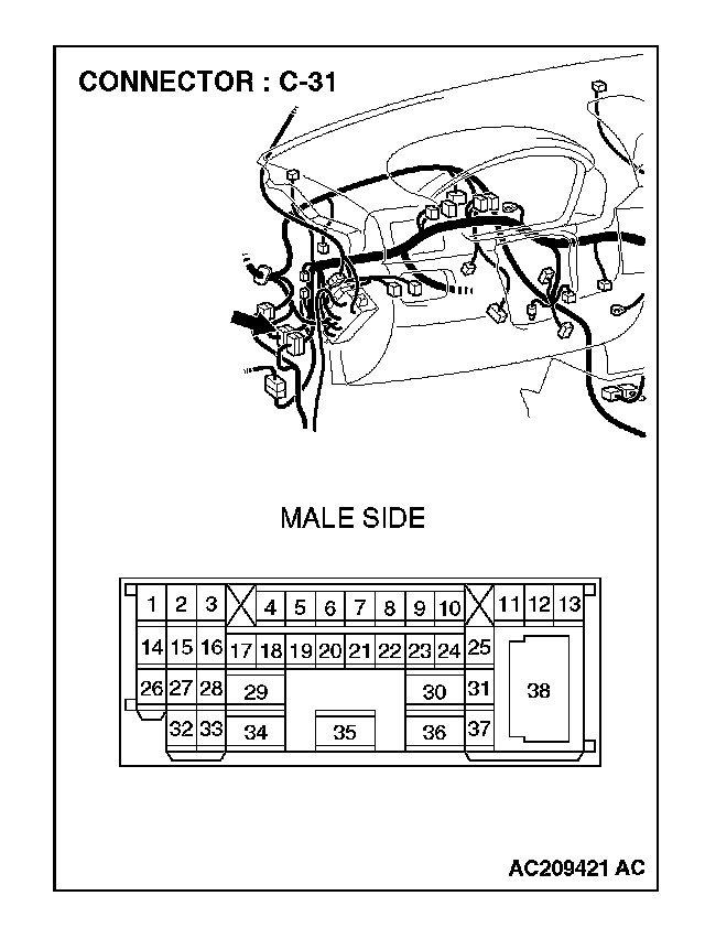
CAUTION: The strand end of the twist wire should be within 10 cm (4 inches) from the connector.
Q: Is intermediate connector C-31 in good condition?
YES: Go to Step 28.
NO: Repair the damaged parts.
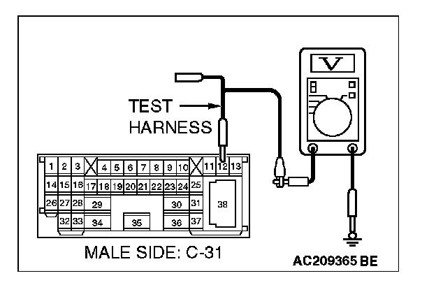
STEP 28. Check the CAN_L-side bus line (communication line including) of the front wiring harness for a short to the power supply. Measure the voltage at intermediate connector C-31.
CAUTION:
- A digital multimeter should be used.
- The test wiring harness should be used.
1. Disconnect intermediate connector C-31, and measure the voltage at the male side (at front wiring harness side).
2. Turn the ignition switch to the "ON" position.
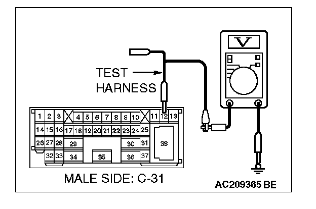
3. Measure the voltage between intermediate connector C-31 terminal 12 and body ground.
OK: 4.0 V or less
Q: Does the voltage measure 4.0 V or less?
YES:
NO:
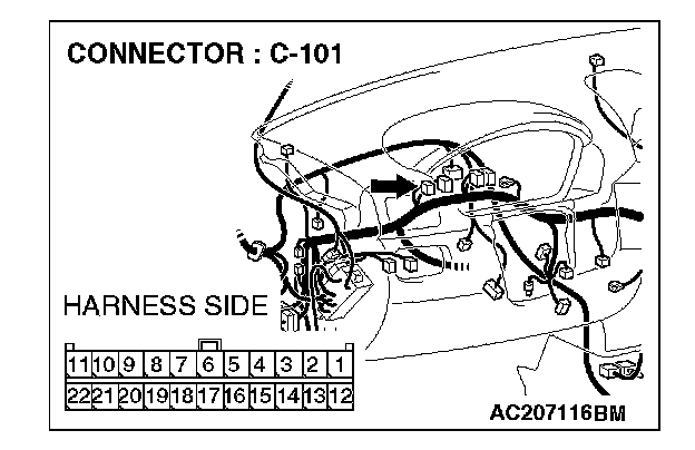
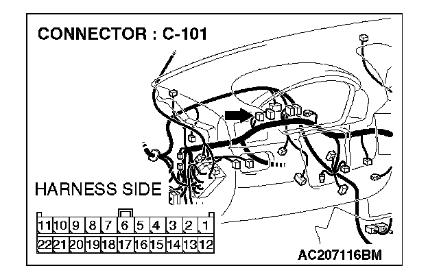
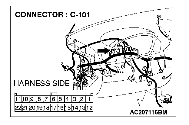
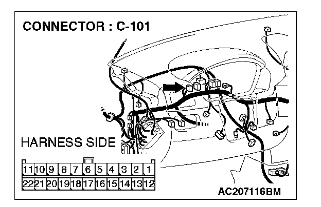
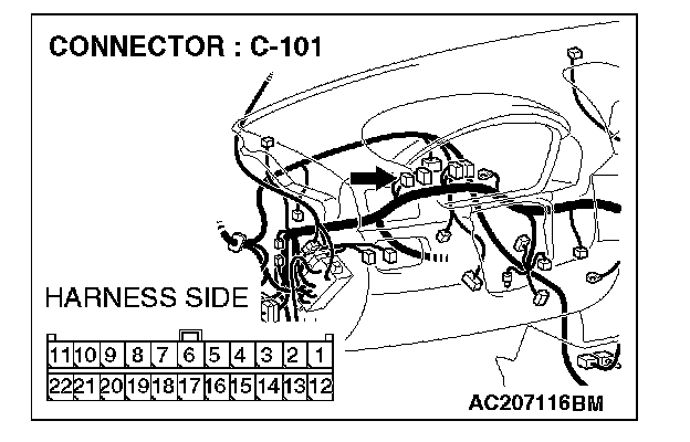
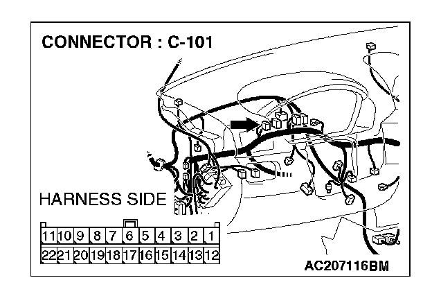
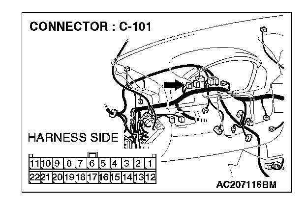
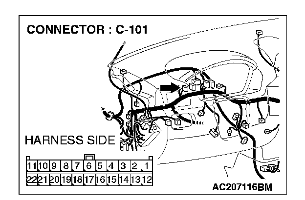
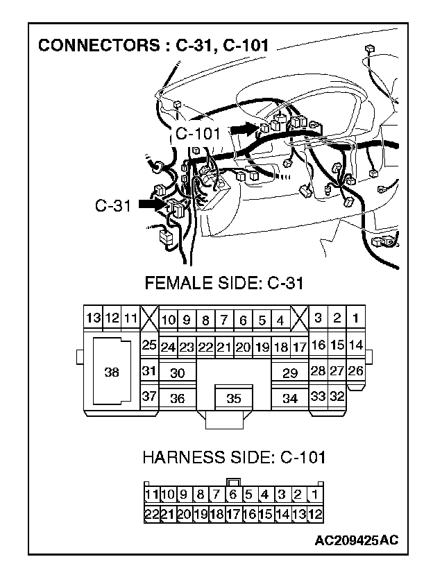
STEP 29. Check joint connector (4) C-101 for loose, corroded or damaged terminals, or terminals pushed back in the connector.
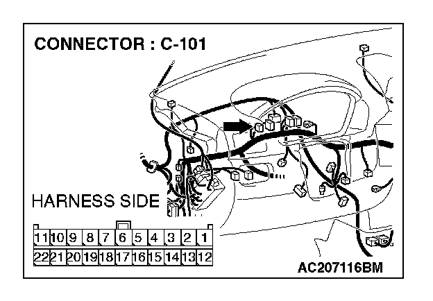
NOTE: For the removal of the joint connector, refer to "How To Disconnect Joint Connector".
CAUTION: The strand end of the twist wire should be within 10 cm (4 inches) from the connector.
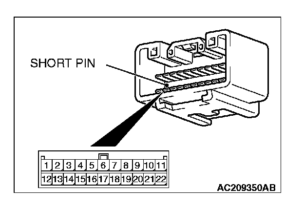
Check the joint connector at the wiring harness side for loose,corroded or damaged terminals, or terminals pushed back in the connector, and also check the short pin behind the connector for corrosion, deformation and delamination.
Q: Is joint connector (4) C-101 in good condition?
YES: Go to Step 30.
NO: Repair the damaged parts. Replace the joint connector as necessary.
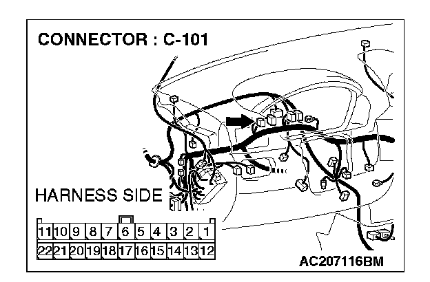
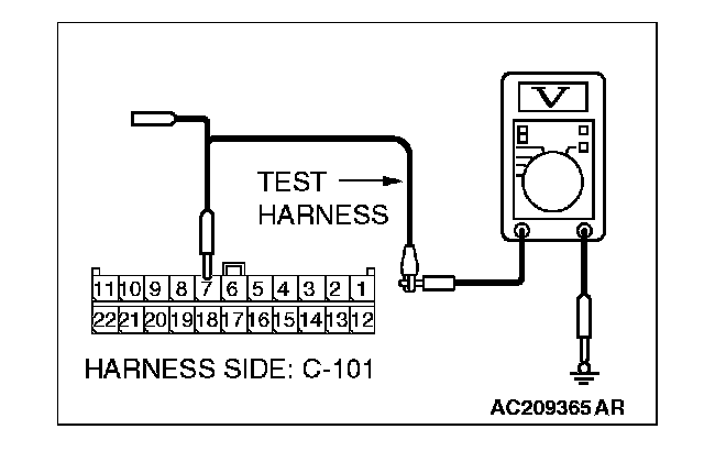
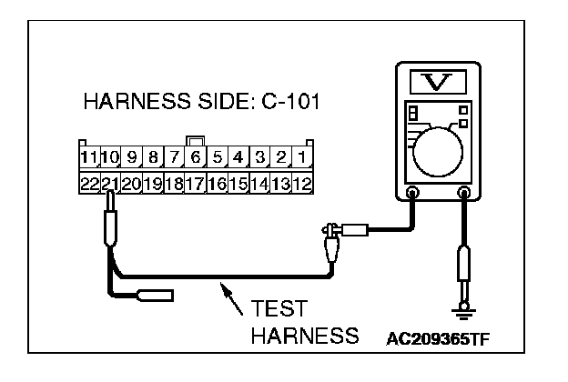
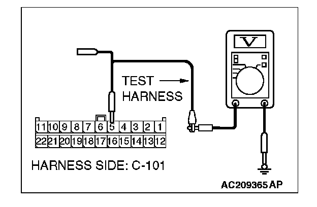
STEP 30. Check the CAN_L line (communication line including the combination meter) between joint connector (4) and the combination meter connector for a short to the power supply. Measure the voltage at joint connector (4) C-101.
CAUTION:
- A digital multimeter should be used.
- The test wiring harness should be used.

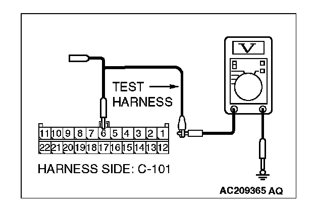
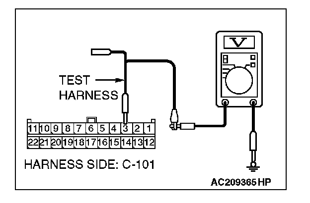
1. Disconnect joint connector (4) C-101, and measure the voltage at the wiring harness side of joint connector (4) C-101.
2. Turn the ignition switch to the "ON" position.
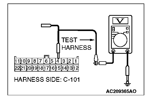
3. Measure the voltage between joint connector (4) terminal 4 and body ground.
OK: 4.0 V or less
Q: Does the voltage measure 4.0 V or less?
YES:
NO:
STEP 31. Check the CAN_L line (communication line only) between joint connector (4) and the combination meter connector for a short to the power supply. Measure the voltage at joint connector (4) C-101.
CAUTION:
- A digital multimeter should be used.
- The test wiring harness should be used.
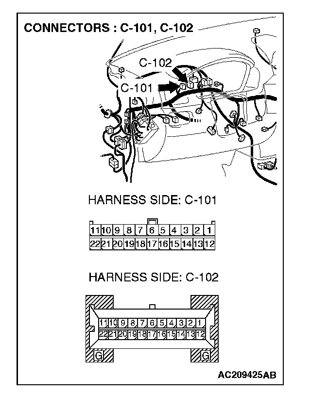
1. Disconnect joint connector (4) C-101 and combination meter connector C-102, and measure the voltage at the wiring harness side of joint connector (4) C-101.
2. Turn the ignition switch to the "ON" position.
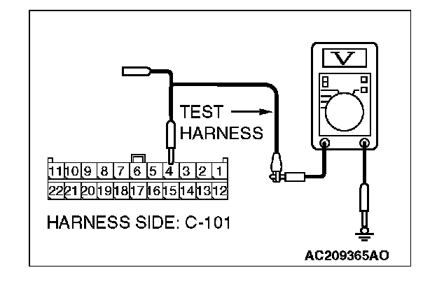
3. Measure the voltage between joint connector (4) terminal 4 and body ground.
OK: 1.0 V or less
CAUTION: Strictly observe the specified wiring harness repair procedure.
Q: Does the voltage measure 1.0 V or less?
YES:
NO:
STEP 32. Check the CAN_L line (communication line including the ETACS-ECU) between joint connector (4) and the ETACS-ECU connector for a short to the power supply. Measure the voltage at joint connector (4) C-101.
CAUTION:
- A digital multimeter should be used.
- The test wiring harness should be used.
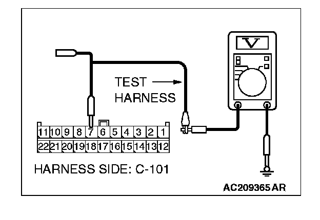
1. Disconnect joint connector (4) C-101, and measure the voltage at the wiring harness side of joint connector (4) C-101.
2. Turn the ignition switch to the "ON" position.
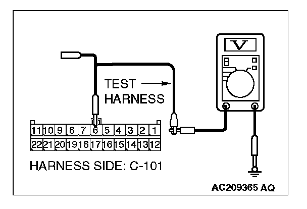
3. Measure the voltage between joint connector (4) terminal 6 and body ground.
OK: 4.0 V or less
Q: Does the voltage measure 4.0 V or less?
YES:
NO:
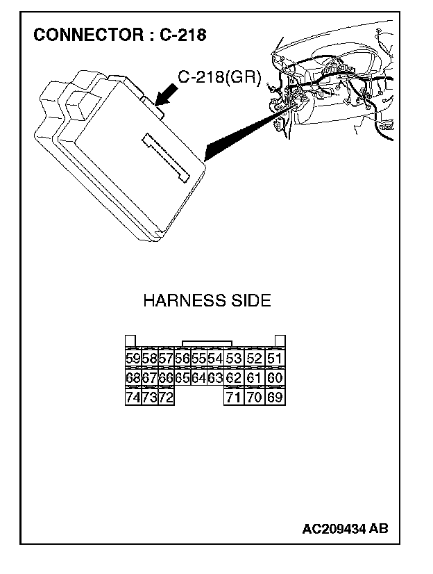
STEP 33. Check ETACS-ECU connector C-218 for loose,corroded or damaged terminals, or terminals pushed back in the connector.
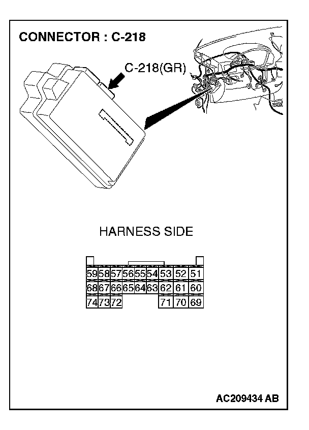
CAUTION: The strand end of the twist wire should be within 10 cm (4 inches) from the connector.
Q: Is ETACS-ECU connector C-218 in good condition?
YES: Go to Step 34.
NO: Repair the damaged parts.
STEP 34. Check the CAN_L line (communication line only) between joint connector (4) and ETACS-ECU connector fora short to the power supply. Measure the voltage at joint connector (4) C-101.
CAUTION:
- A digital multimeter should be used.
- The test wiring harness should be used.
1. Disconnect joint connector (4) C-101 and ETACS-ECU connector C-218, and measure the voltage at the wiring harness side of joint connector (4) C-101.
2. Turn the ignition switch to the "ON" position.
3. Measure the voltage between joint connector (4) terminal 6 and body ground.
OK: 1.0 V or less
CAUTION: Strictly observe the specified wiring harness repair procedure.
Q: Does the voltage measure 1.0 V or less?
YES:
NO:
STEP 35. Check the CAN_L line (communication line including the A/C-ECU) between joint connector (4) and the A/C-ECU connector for a short to the power supply. Measure the voltage at joint connector (4) C-101.
CAUTION:
- A digital multimeter should be used.
- The test wiring harness should be used.
1. Disconnect joint connector (4) C-101, and measure the voltage at the wiring harness side of joint connector (4) C-101.
2. Turn the ignition switch to the "ON" position.
3. Measure the voltage between joint connector (4) terminal 7 and body ground.
OK: 4.0 V or less
Q: Does the voltage measure 4.0 V or less
YES:
NO:
STEP 36. Check A/C-ECU connector C-42
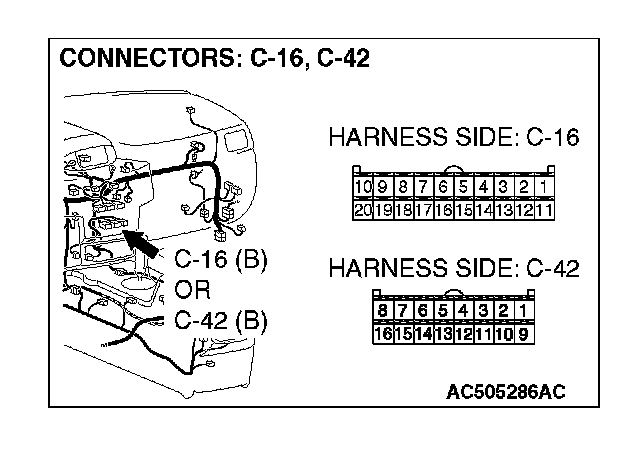
CAUTION: The strand end of the twist wire should be within 10 cm (4 inches) from the connector.
Q: Is A/C-ECU connector C-42
YES: Go to Step 37.
NO: Repair the damaged parts.
STEP 37. Check the CAN_L line (communication line only) between joint connector (4) and A/C-ECU connector for a short to the power supply. Measure the voltage at joint connector (4) C-101.
CAUTION:
- A digital multimeter should be used.
- The test wiring harness should be used.
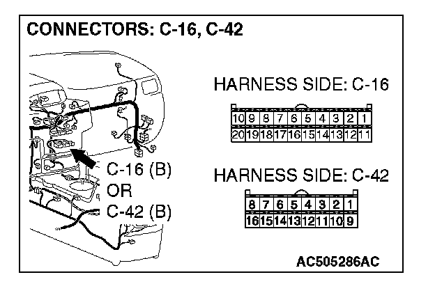
1. Disconnect joint connector (4) C-101 and A/C-ECU connector C-42
2. Turn the ignition switch to the "ON" position.
3. Measure the voltage between joint connector (4) terminal 7 and body ground.
OK: 1.0 V or less
CAUTION: Strictly observe the specified wiring harness repair procedure.
Q: Does the voltage measure 1.0 V or less?
YES:
NO:
STEP 38. Check the CAN_L line (communication line including the SRS-ECU) between joint connector (4) and the SRS-ECU connector for a short to the power supply. Measure the voltage at joint connector (4) C-101.
CAUTION:
- A digital multimeter should be used.
- The test wiring harness should be used.
1. Disconnect joint connector (4) C-101, and measure the voltage at the wiring harness side of joint connector (4) C-101.
2. Turn the ignition switch to the "ON" position.
3. Measure the voltage between joint connector (4) terminal 3 and body ground.
OK: 4.0 V or less
Q: Does the voltage measure 4.0 V or less?
YES:
NO:
STEP 39. Check SRS-ECU connector C-26 for loose, corroded or damaged terminals, or terminals pushed back in the connector.
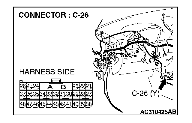
CAUTION: The strand end of the twist wire should be within 10 cm (4 inches) from the connector.
Q: Is SRS-ECU connector C-26 in good condition?
YES: Go to Step 40.
NO: Repair the damaged parts.
STEP 40. Check the CAN_L line (communication line only) between joint connector (4) and SRS-ECU connector for a short to the power supply. Measure the voltage at joint connector (4) C-101.
CAUTION:
- A digital multimeter should be used.
- The test wiring harness should be used.
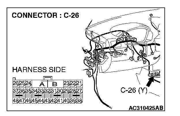
1. Disconnect joint connector (4) C-101 and SRS-ECU connector C-26, and measure the voltage at the wiring harness side of joint connector (4) C-101.
2. Turn the ignition switch to the "ON" position.

3. Measure the voltage between joint connector (4) terminal 3 and body ground.
OK: 1.0 V or less
CAUTION: Strictly observe the specified wiring harness repair procedure.
Q: Does the voltage measure 1.0 V or less?
YES:
NO:
STEP 41. Check the CAN_L line (communication line including the TPMS receiver) between joint connector (4) and the TPMS receiver connector for short to the power supply. Measure the voltage at joint connector (4) C-101.
CAUTION:
- A digital multimeter should be used.
- The test wiring harness should be used.
1. Disconnect joint connector (4) C-101, and measure the voltage at the wiring harness side of joint connector (4) C-101.
2. Turn the ignition switch to the "ON" position.
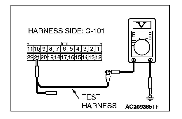
3. Measure the voltage between joint connector (4) terminals 21 and body ground.
OK: 4.0 V or less
Q: Does the voltage measure 4.0 V or less?
YES: If the voltage measures 4.0 V or less, go to Step 47.
NO: If the voltage measures more than 4.0 V, go to Step 42.
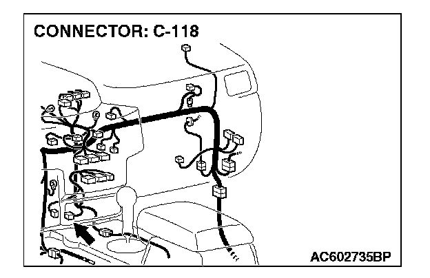
STEP 42. Check TPMS receiver connector C-118 for loose, corroded or damaged terminals, or terminals pushed back in the connector.
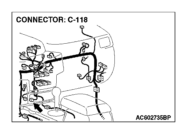
CAUTION: The strand end of the twisted wire should be within 10 cm (4 inches) from the connector.
Q: Is TPMS receiver connector C-118 in good condition?
YES: Go to Step 43.
NO: Repair the damaged parts.
STEP 43. Check the CAN_L line (communication line only) between joint connector (4) and TPMS receiver connector for a short to the power supply. Measure the voltage at joint connector (4) C-101.
CAUTION:
- A digital multimeter should be used.
- The test wiring harness should be used.
1. Disconnect joint connector (4) C-101 and TPMS receiver connector C-118, and measure the voltage at the male side of joint connector (4) C-101.
2. Turn the ignition switch to the "ON" position.
3. Measure the voltage between joint connector (4) terminals 21 and body ground.
OK: 1.0 V or less
CAUTION: Strictly observe the specified wiring harness repair procedure.
Q: Does the voltage measure 1.0 V or less?
YES: If the voltage measures 1.0 V or less, diagnose CAN bus lines thoroughly by referring to Diagnostic Item 9. Diagnostic Item 9
NO: joint connector (3) and the TPMS receiver connector.
STEP 44. Check the CAN_L line (communication line only) between joint connector (4) and the data link connector for a short to the power supply. Measure the voltage at joint connector (4) C-101.
CAUTION:
- A digital multimeter should be used.
- The test wiring harness should be used.
1. Disconnect joint connector (4) C-101, and measure the voltage at the wiring harness side of joint connector (4) C-101.
2. Turn the ignition switch to the "ON" position.
3. Measure the voltage between joint connector (4) terminal 5and body ground.
OK: 1.0 V or less
CAUTION: Strictly observe the specified wiring harness repair procedure.
Q: Does the voltage measure 1.0 V or less?
YES:
NO:
STEP 45. Check the CAN_L line (communication line only) between intermediate connector C-31 and joint connector(4) for a short to the power supply. Measure the voltage at joint connector (4) C-101.
CAUTION:
- A digital multimeter should be used.
- The test wiring harness should be used.
1. Disconnect intermediate connector C-31 and joint connector (4) C-101, and measure the voltage at the wiring harness side of joint connector (4) C-101.
2. Turn the ignition switch to the "ON" position.
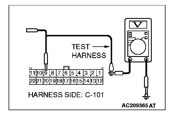
3. Measure the voltage between joint connector (4) terminal 9and body ground.
OK: 1.0 V or less
CAUTION: Strictly observe the specified wiring harness repair procedure.
Q: Does the voltage measure 1.0 V or less?
YES:
NO:
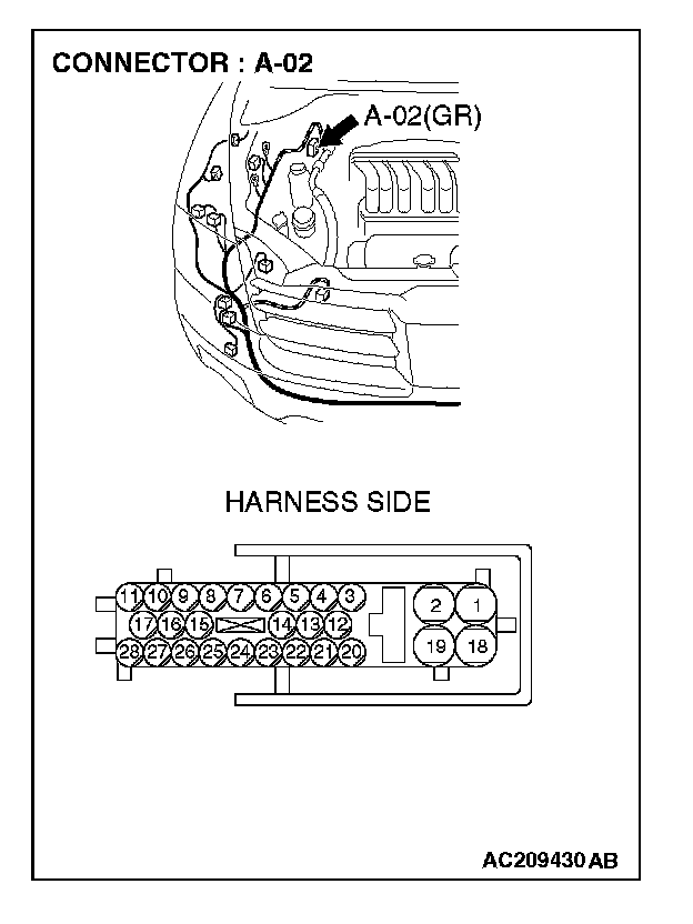
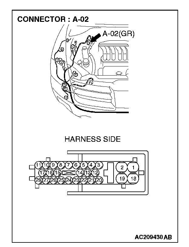
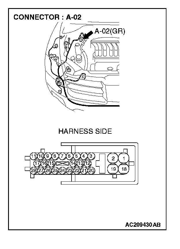
STEP 46. Check ABS/TCL-ECU connector A-02 for loose, corroded or damaged terminals, or terminals pushed back in the connector.
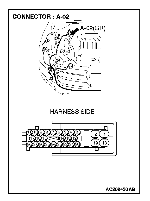
CAUTION: The strand end of the twist wire should be within 10 cm (4 inches) from the connector.
Q: Is ABS/TCL-ECU connector A-02 in good condition?
YES: Go to Step 47.
NO: Repair the damaged parts.
STEP 47. Check the CAN_L line (communication line only) between intermediate connector C-31 and ABS/TCL-ECU connector for a short to the power supply. Measure the voltage at intermediate connector C-31.
CAUTION:
- A digital multimeter should be used.
- The test wiring harness should be used.
1. Disconnect intermediate connector C-31 and ABS/TCL-ECU connector A-02, and measure the voltage at the male side of intermediate connector C-31 (at front wiring harness side).
2. Turn the ignition switch to the "ON" position.
3. Measure the voltage between intermediate connector C-31 terminal 12 and body ground.
OK: 1.0 V or less
CAUTION: Strictly observe the specified wiring harness repair procedure.
Q: Does the voltage measure 1.0 V or less?
YES:
NO:
STEP 48. Check the CAN_L line (communication line only) between the powertrain control module connector and ABS/TCL-ECU connector for a short to the power supply. Measure voltage at powertrain control module connector B-18.
CAUTION:
- A digital multimeter should be used.
- The test wiring harness should be used.
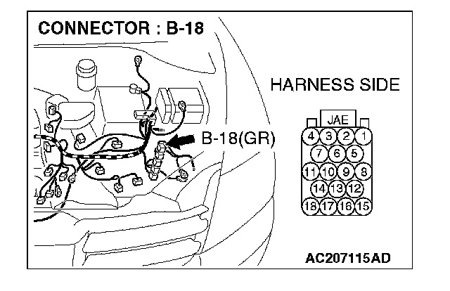
1. Disconnect powertrain control module connector B-18 and ABS/TCL-ECU connector A-02, and measure the voltage at the harness side of powertrain control module connector B-18.
2. Turn the ignition switch to the "ON" position.
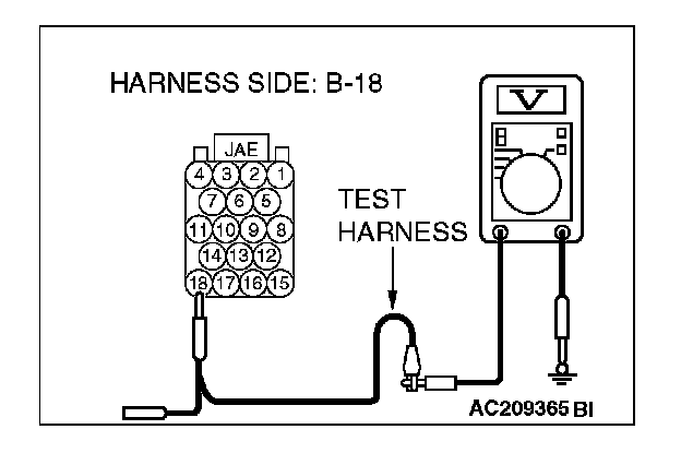
3. Measure the voltage between powertrain control module connector terminal 18 and body ground.
OK: 1.0 V or less
CAUTION: Strictly observe the specified wiring harness repair procedure.
Q: Does the voltage measure 1.0 V or less?
YES:
NO:
STEP 49. Check the CAN_L line inside the ABS/TCL-ECU for a short to the power supply. Measure the voltage at ABS/TCL-ECU connector A-02.
CAUTION:
- A digital multimeter should be used.
- The test wiring harness should be used.
1. Disconnect ABS/TCL-ECU connector A-02.
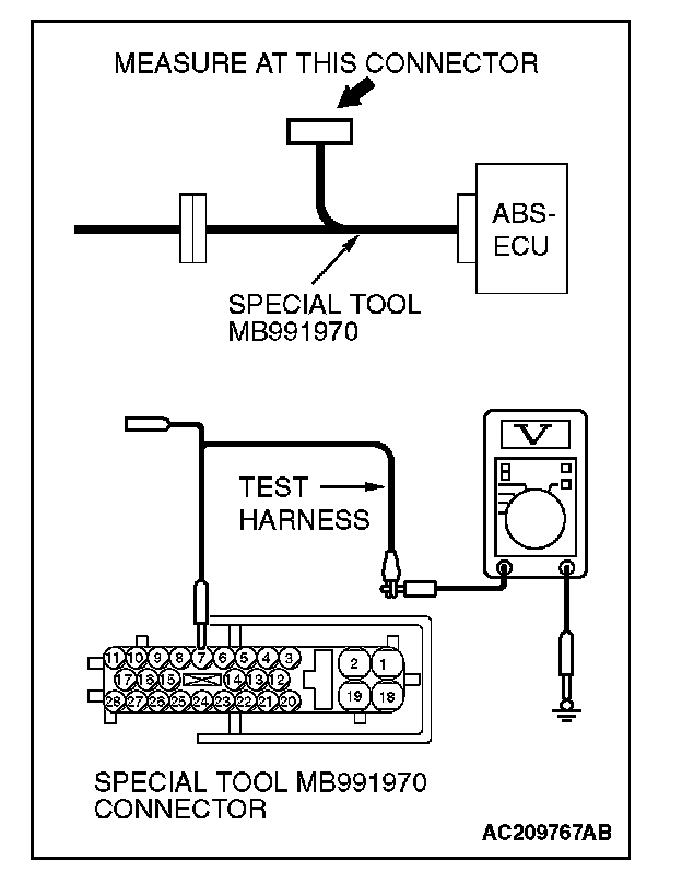
2. Connect special tool MB991970 (ABS check harness) to the ABS/TCL-ECU and the wiring harness, and measure the voltage at special tool MB991970 (ABS check harness).
3. Turn the ignition switch to the "ON" position.
4. Measure the voltage between special tool MB991970 (ABS check harness) connector terminal 7 and body ground.
OK: 4.0 V or less
Q: Does the voltage measure 4.0 V or less?
YES:
NO: