Part 2
STEP 23. Check the TPMS receiver for short circuit. Measure the resistance at TPMS receiver connector C-118.CAUTION: A digital multimeter should be used.
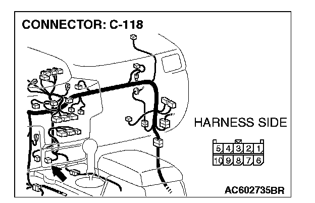
1. Disconnect TPMS receiver connector C-118, and measure the resistance at the component side of TPMS receiver connector C-118.
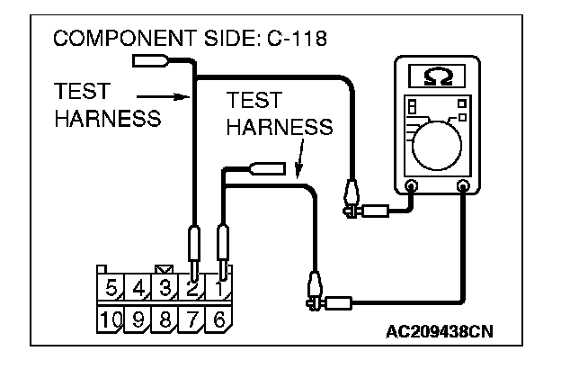
2. Measure the resistance between TPMS receiver connector terminals 1 and 2.
OK: 1 kohm or more
Q: Does the resistance measure 1 kohm or more?
YES: If the resistance measures 1 kohm or more, diagnose CAN bus lines thoroughly by referring to Diagnostic Item 9. Diagnostic Item 9
NO: If the resistance measures less than 1 kohm, replace the TPMS receiver.
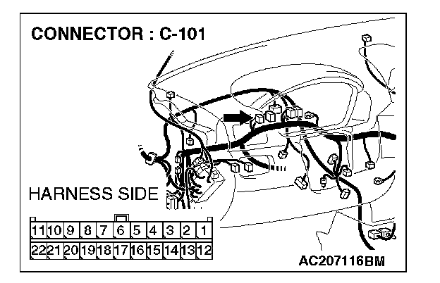
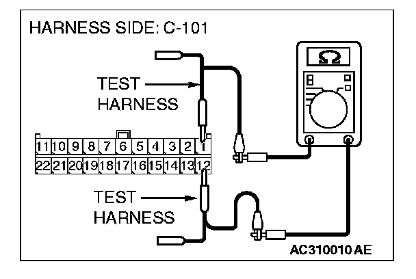
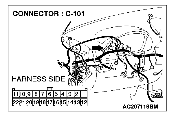
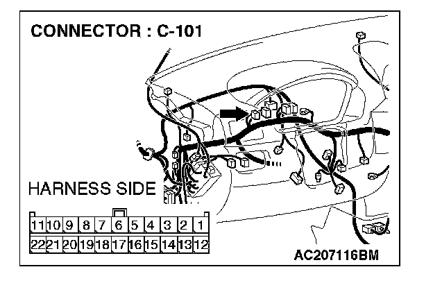
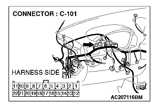
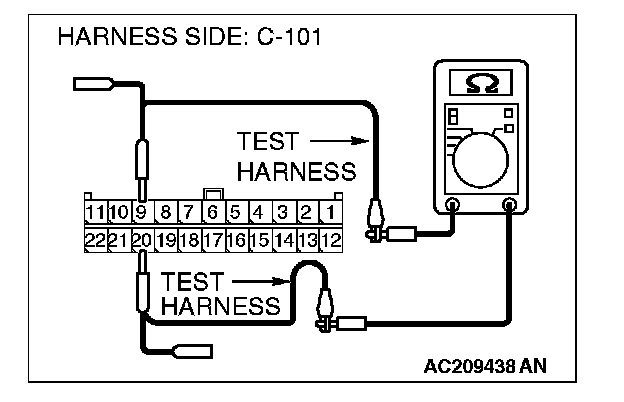
STEP 24. Check the CAN_L and H lines (communication lines including the G and yaw rate sensor) between joint connector (4) and the G and yaw rate sensor for short circuit. Measure the resistance at joint connector (4) C-101.
CAUTION:
- A digital multimeter should be used.
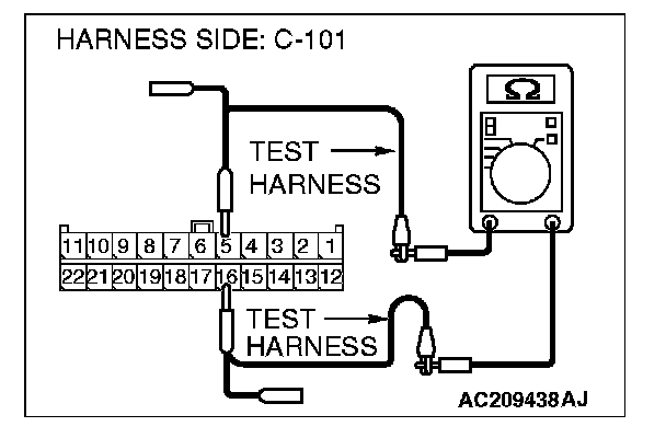
- The test wiring harness should be used.
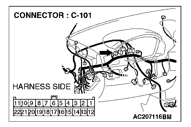
1. Disconnect joint connector (4) C-101, and measure the resistance at the wiring harness side of joint connector (4) C-101.
2. Turn the ignition switch to the "LOCK" (OFF) position.
CAUTION: Disconnect the negative battery terminal.
3. Disconnect the negative battery terminal.
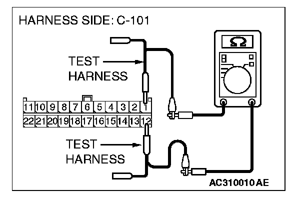
4. Measure the resistance between joint connector (4) terminals 1 and 12.
OK: 1 kohm or more
Q: Does the resistance measure 1 kohm or more?
YES:
NO:
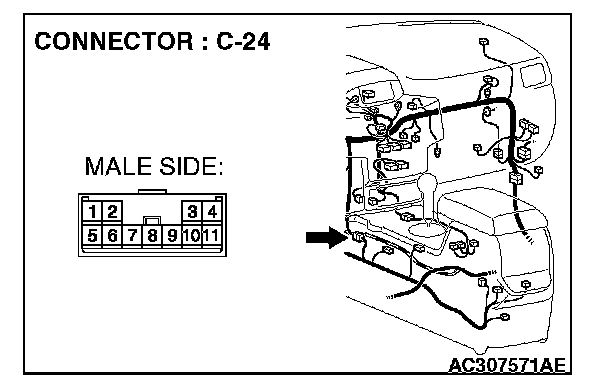
STEP 25. Check G and yaw rate sensor connector C-36 and intermediate connector C-24 for loose, corroded or damaged terminals, or terminals pushed back in the connector.
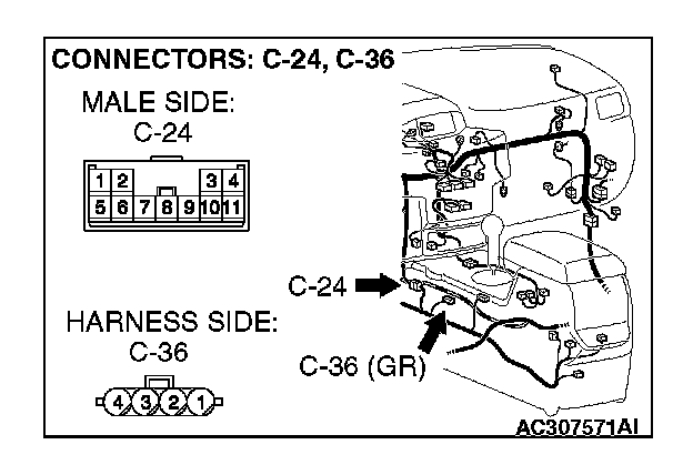
CAUTION: The strand end of the twist wire should be within 10 cm (4 inches) from the connector.
Q: Are G and yaw rate sensor connector C-36 and intermediate connector C-24 in good condition?
YES: Go to Step 26.
NO: Repair the damaged parts.
STEP 26. Check the CAN_L and H lines (communication lines only) between intermediate connector and the G and yaw rate sensor for short circuit. Measure the resistance at intermediate connector C-24.
CAUTION:
- A digital multimeter should be used.
- The test wiring harness should be used.
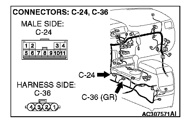
1. Disconnect intermediate connector C-24 and G and yaw rate sensor connector C-36, and measure the resistance at the wiring harness side of intermediate connector C-24.
2. Turn the ignition switch to the "LOCK" (OFF) position.
CAUTION: Disconnect the negative battery terminal.
3. Disconnect the negative battery terminal.
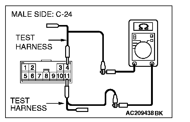
4. Measure the resistance between intermediate connector terminals 4 and 11.
OK: 1 kohm or more
CAUTION: Strictly observe the specified wiring harness repair procedure.
Q: Does the resistance measure 1 kohm or more?
YES:
NO:
STEP 27. Check the G and yaw rate sensor for short circuit. Measure the resistance at G and yaw rate sensor connector C-36.
CAUTION: A digital multimeter should be used.
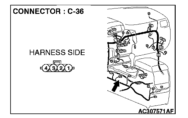
1. Disconnect G and yaw rate sensor connector C-36, and measure the resistance at the equipment side of G and yaw rate sensor connector C-36.
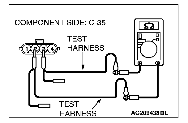
2. Measure the resistance between the G and yaw rate sensor connector terminals 2 and 3.
OK: 1 kohm or more
Q: Does the resistance measure 1 kohm or more?
YES:
NO:
STEP 28. Check the CAN_L and H lines (communication lines only) between joint connector (4) and the intermediate connector for short circuit. Measure the resistance at joint connector (4) C-101.
CAUTION:
- A digital multimeter should be used.
- The test wiring harness should be used.
1. Disconnect intermediate connector C-24 and joint connector (4) C-101, and measure the resistance at the wiring harness side of joint connector (4) C-101.
2. Turn the ignition switch to the "LOCK" (OFF) position.
CAUTION: Disconnect the negative battery terminal.
3. Disconnect the negative battery terminal.
4. Measure the resistance between joint connector (4) terminals 1 and 12.
OK: 1 kohm or more
CAUTION: Strictly observe the specified wiring harness repair procedure.
Q: Does the resistance measure 1 kohm or more?
YES:
NO:
STEP 29. Check the CAN_L and H lines (communication lines including the steering wheel sensor) between joint connector (4) and the steering wheel sensor for short circuit. Measure the resistance at joint connector (4) C-101.
CAUTION:
- A digital multimeter should be used.
- The test wiring harness should be used.
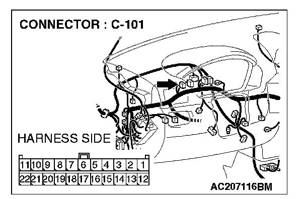
1. Disconnect joint connector (4) C-101, and measure the resistance at the wiring harness side of joint connector (4) C-101.
2. Turn the ignition switch to the "LOCK" (OFF) position.
CAUTION: Disconnect the negative battery terminal.
3. Disconnect the negative battery terminal.
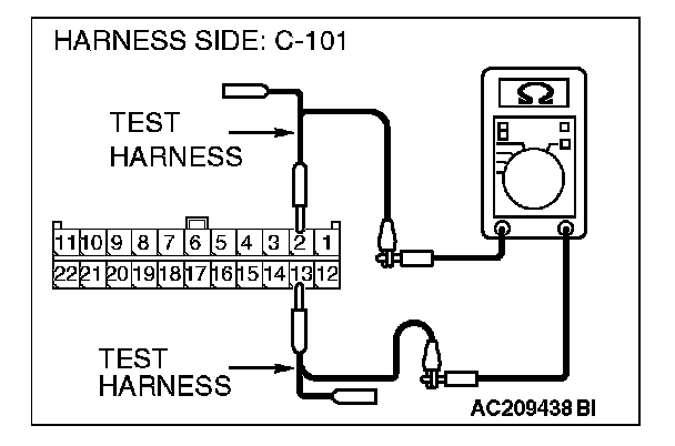
4. Measure the resistance between joint connector (4) terminals 2 and 13.
OK: 1 kohm or more
Q: Does the resistance measure 1 kohm or more?
YES:
NO:
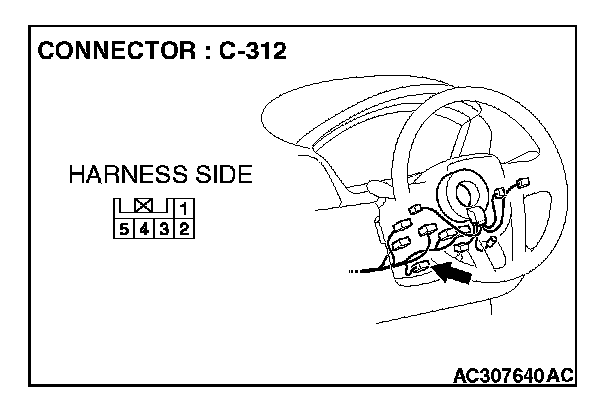
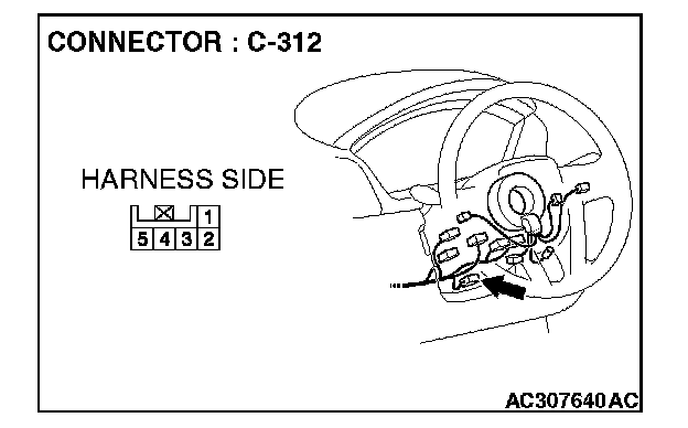
STEP 30. Check steering wheel sensor connector C-312 for loose, corroded or damaged terminals, or terminals pushed back in the connector.
CAUTION: The strand end of the twist wire should be within 10 cm (4 inches) from the connector.
Q: Is steering wheel sensor connector C-312 in good condition?
YES: Go to Step 31.
NO: Repair the damaged parts.
STEP 31. Check the CAN_L and H lines (communication lines only) between joint connector (4) and the steering wheel sensor for short circuit. Measure the resistance at joint connector (4) C-101.
CAUTION:
- A digital multimeter should be used.
- The test wiring harness should be used.

1. Disconnect joint connector (4) C-101 and steering wheel sensor connector C-312, and measure the resistance at the wiring harness side of joint connector (4) C-101.
2. Turn the ignition switch to the "LOCK" (OFF) position.
CAUTION: Disconnect the negative battery terminal.
3. Disconnect the negative battery terminal.
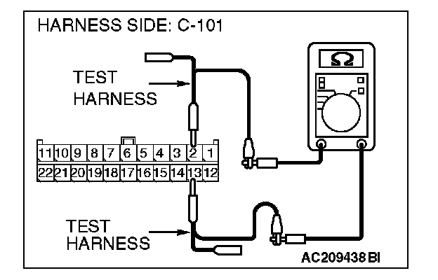
4. Measure the resistance between joint connector (4) terminals 2 and 13.
OK: 1 kohm or more
CAUTION: Strictly observe the specified wiring harness repair procedure.
Q: Does the resistance measure 1 kohm or more?
YES:
NO:
STEP 32. Check the steering wheel sensor for short circuit. Measure the resistance at steering wheel sensor connector C-312.
CAUTION: A digital multimeter should be used.
1. Disconnect steering wheel sensor connector C-312, and measure the resistance at the equipment side of steering wheel sensor connector C-312.
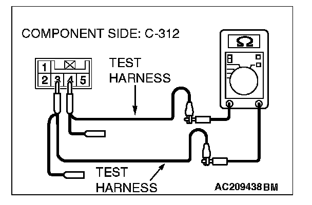
2. Measure the resistance between the steering wheel sensor connector terminals 3 and 4.
OK: 1 kohm or more
Q: Does the resistance measure 1 kohm or more?
YES:
NO:
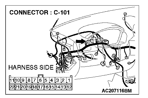
STEP 33. Check the CAN_L and H lines (communication lines including the multi-center display unit (middle-grade type or vehicles with Mitsubishi multi communication system)) between joint connector (4) and the multi-center display for short circuit. Measure the resistance at joint connector (4) C-101.
CAUTION:
- A digital multimeter should be used.
- The test wiring harness should be used.
1. Disconnect joint connector (4) C-101, and measure the resistance at the wiring harness side of joint connector (4) C-101.
2. Turn the ignition switch to the "LOCK" (OFF) position.
CAUTION: Disconnect the negative battery terminal.
3. Disconnect the negative battery terminal.
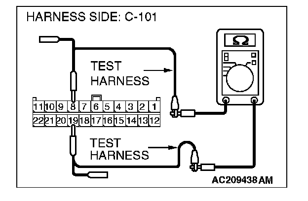
4. Measure the resistance between joint connector (4) terminals 8 and 19.
OK: 1 kohm or more
Q: Does the resistance measure 1 kohm or more?
YES:
NO:
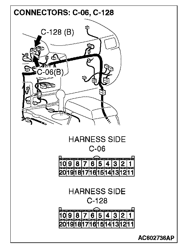
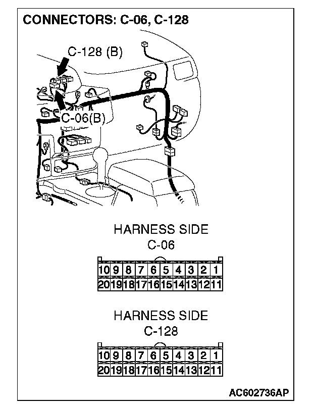
STEP 34. Check multi-center display unit (middle-grade type or vehicles with Mitsubishi multi communication system) connector C-06
CAUTION: The strand end of the twist wire should be within 10 cm (4 inches) from the connector.
Q: Is multi-center display unit (middle-grade type or vehicles with Mitsubishi multi communication system) connector C-06
YES: Go to Step 35.
NO: Repair the damaged parts.
STEP 35. Check the CAN_L and H lines (communication lines only) between joint connector (4) and the multi-center display unit (middle-grade type or vehicles with Mitsubishi multi communication system) for short circuit. Measure the resistance at joint connector (4) C-101.
CAUTION:
- A digital multimeter should be used.
- The test wiring harness should be used.
1. Disconnect joint connector (4) C-101 and multi-center display unit (middle-grade type or vehicles with Mitsubishi multi communication system) connector C-06
2. Turn the ignition switch to the "LOCK" (OFF) position.
CAUTION: Disconnect the negative battery terminal.
3. Disconnect the negative battery terminal.
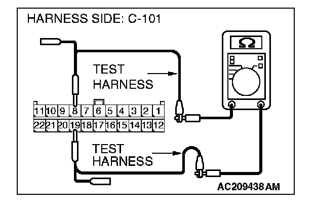
4. Measure the resistance between joint connector (4) terminals 8 and 19.
OK: 1 kohm or more
CAUTION: Strictly observe the specified wiring harness repair procedure.
Q: Does the resistance measure 1 kohm or more?
YES:
NO:
STEP 36. Check the multi-center display unit (middle-grade type or vehicles with Mitsubishi multicommunication system) for short circuit. Measure the resistance at multi-center display unit (middle-grade type or vehicles with Mitsubishi multi communication system) connector C-06
CAUTION: A digital multimeter should be used.
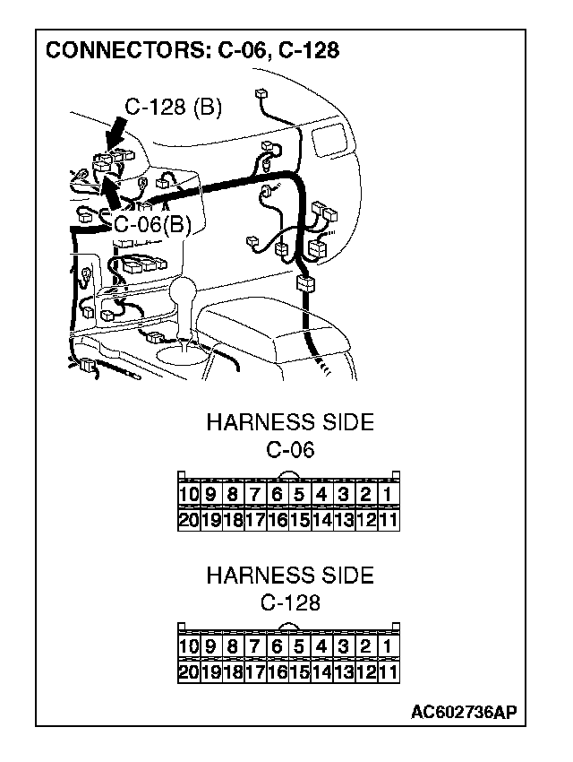
1. Disconnect multi-center display unit (middle-grade type or vehicles with Mitsubishi multi communication system) connector C-06
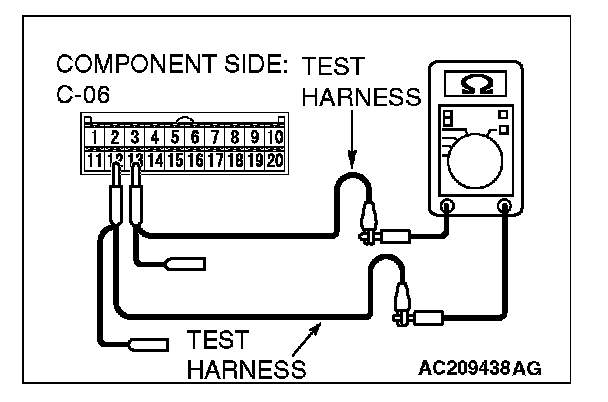
2. Measure the resistance between the multi-center display unit (middle-grade type or vehicles with Mitsubishi multi communication system) connector terminals 12 and 13
OK: 1 kohm or more
Q: Does the resistance measure 1 kohm or more?
YES:
NO:
STEP 37. Check data link connector C-121 for loose, corroded or damaged terminals, or terminals pushed back in the connector.
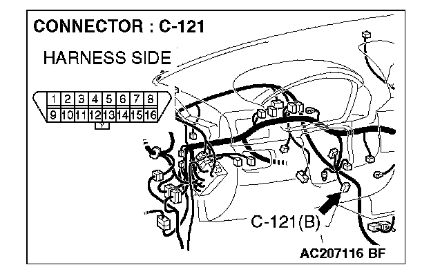
CAUTION: The strand end of the twist wire should be within 10 cm (4 inches) from the connector.
Q: Is data link connector C-121 in good condition?
YES: Go to Step 38.
NO: Repair the damaged parts.
STEP 38. Check the CAN_L and H lines (communication lines only) between joint connector (4) and the data link connector for short circuit. Measure the resistance at joint connector (4) C-101.
CAUTION:
- A digital multimeter should be used.
- The test wiring harness should be used.
1. Disconnect joint connector (4) C-101, and measure the resistance at the wiring harness side of joint connector (4) C-101.
2. Turn the ignition switch to the "LOCK" (OFF) position.
CAUTION: Disconnect the negative battery terminal.
3. Disconnect the negative battery terminal.
4. Measure the resistance between joint connector (4) terminals 5 and 16.
OK: 1 kohm or more
Q: Does the resistance measure 1 kohm or more?
YES:
NO:
STEP 39. Check the CAN_L and H lines (communication lines only) between joint connector (4) and the intermediate connector for short circuit. Measure the resistance at joint connector (4) C-101.
CAUTION:
- A digital multimeter should be used.
- The test wiring harness should be used.
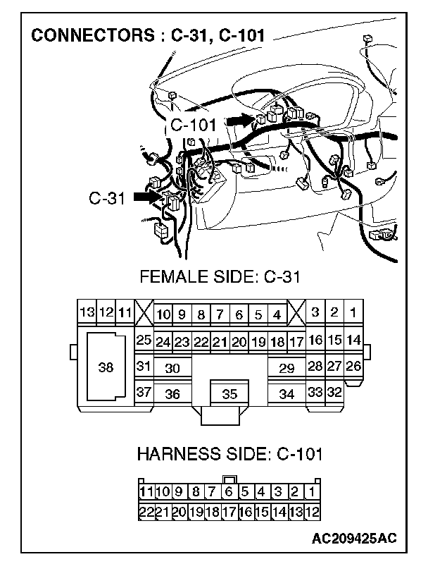
1. Disconnect intermediate connector C-31 and joint connector (4) C-101, and measure the resistance at the wiring harness side of joint connector (4) C-101.
2. Turn the ignition switch to the "LOCK" (OFF) position.
CAUTION: Disconnect the negative battery terminal.
3. Disconnect the negative battery terminal.
4. Measure the resistance between joint connector (4) terminals 9 and 20.
OK: 1 kohm or more
CAUTION: Strictly observe the specified wiring harness repair procedure.
Q: Does the resistance measure 1 kohm or more?
YES:
NO:
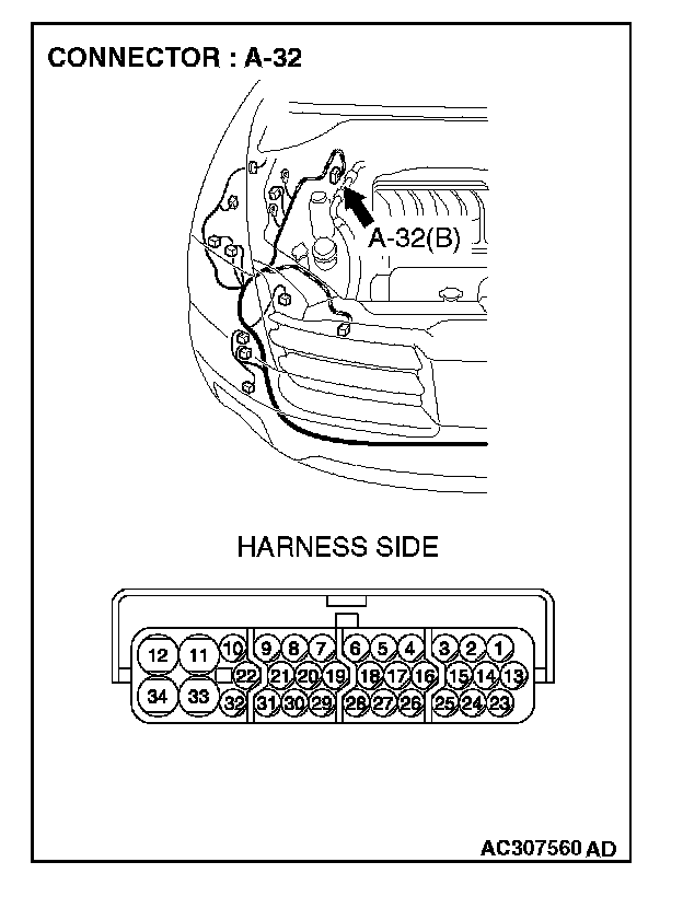
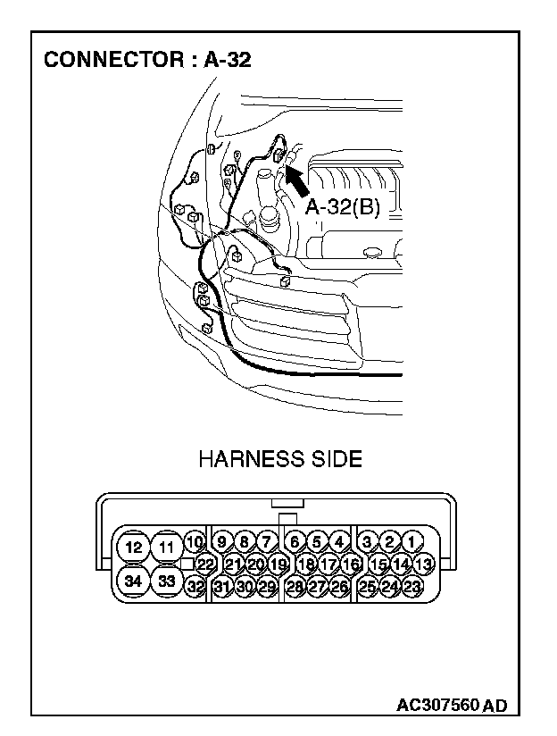
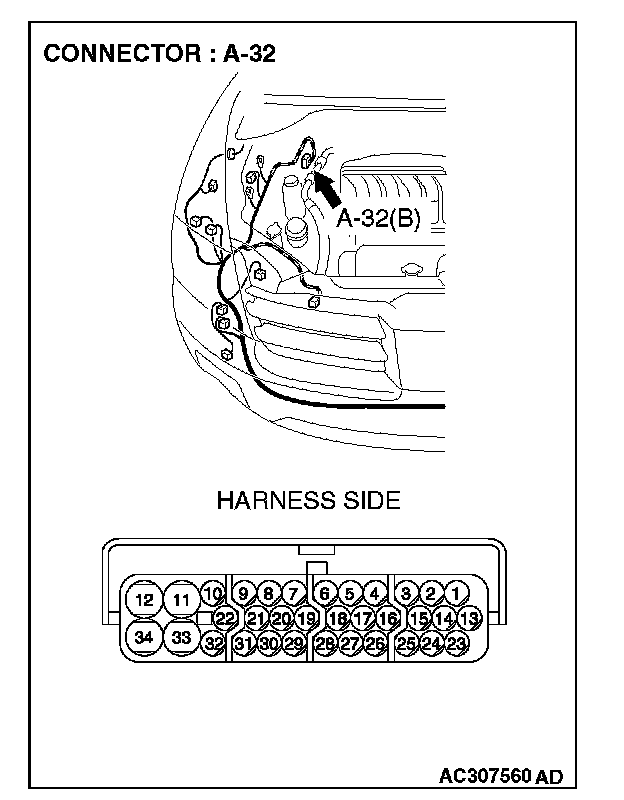
STEP 40. Check ASC/TCL-ECU connector A-32 for loose, corroded or damaged terminals, or terminals pushed back in the connector.
CAUTION: The strand end of the twist wire should be within 10 cm (4 inches) from the connector.
Q: Is ASC/TCL-ECU connector A-32 in good condition?
YES: Go to Step 41.
NO: Repair the damaged parts.
STEP 41. Check the CAN_L and H lines (communication lines only) between the ASC/TCL-ECU connector and the intermediate connector for short circuit. Measure the resistance at intermediate connector C-31.
CAUTION:
- A digital multimeter should be used.
- The test wiring harness should be used.
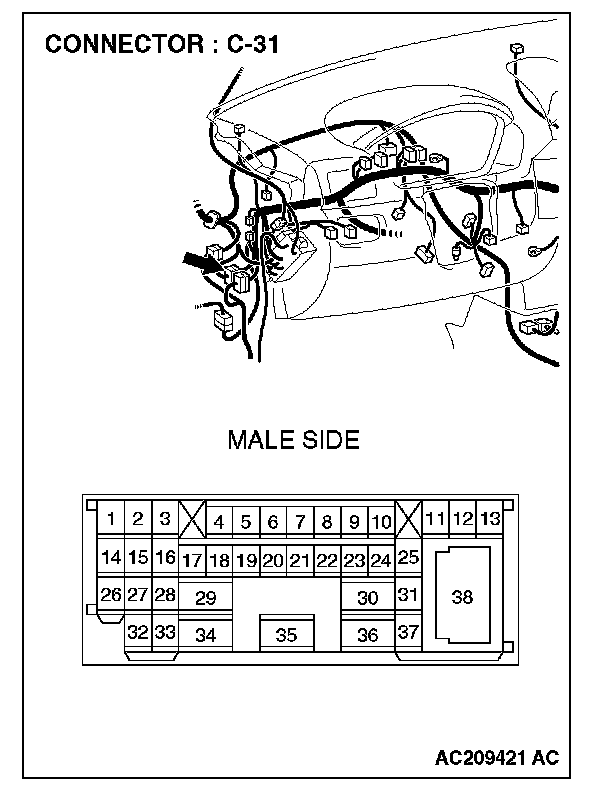
1. Disconnect intermediate connector C-31 and ASC/TCL-ECU connector A-32, and measure the resistance at the male side of intermediate connector C-31(at front wiring harness side).
2. Turn the ignition switch to the "LOCK" (OFF) position.
CAUTION: Disconnect the negative battery terminal.
3. Disconnect the negative battery terminal.
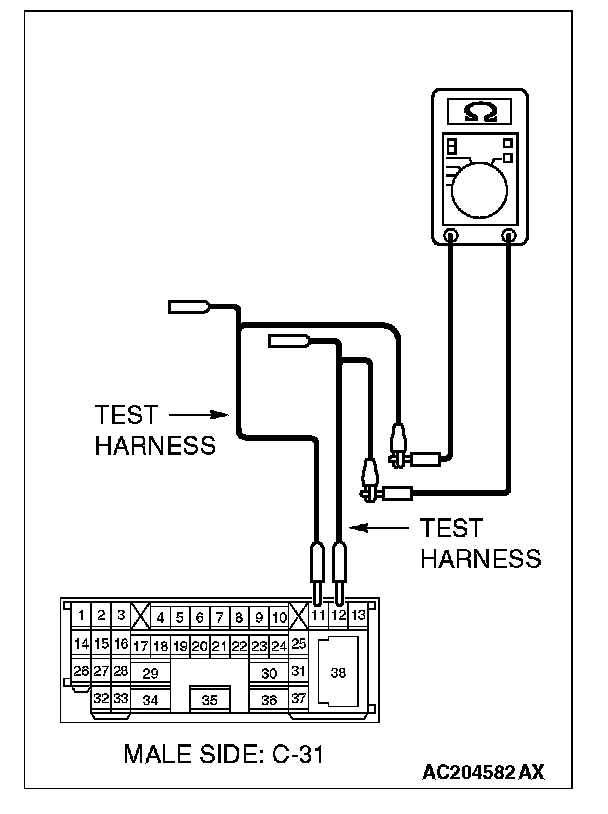
4. Measure the resistance between intermediate connector C-31 terminals 11 and 12.
OK: 1 kohm or more
Q: Does the resistance measure 1 kohm or more?
YES:
NO:
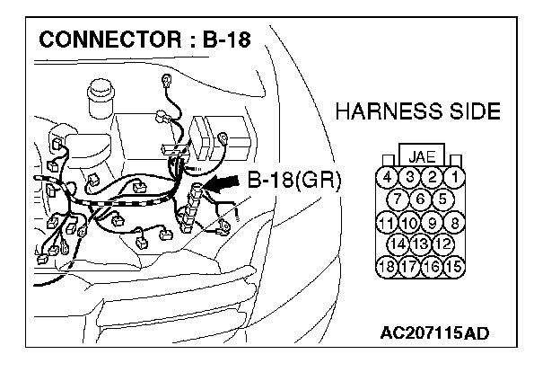
STEP 42. Check powertrain control module connector B-18 for loose, corroded or damaged terminals, or terminals pushed back in the connector.
CAUTION: The strand end of the twist wire should be within 10 cm (4 inches) from the connector.
Q: Is powertrain control module connector B-18 in good condition?
YES: Go to Step 43.
NO: Repair the damaged parts.
STEP 43. Check the CAN_L and H lines (communication lines only) between the powertrain control module connector and the ASC/TCL-ECU connector for short circuit. Measure the resistance at powertrain control module connector B-18.
CAUTION:
- A digital multimeter should be used.
- The test wiring harness should be used.
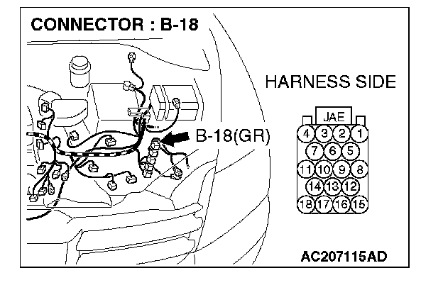
1. Disconnect powertrain control module connector B-18 and ASC/TCL-ECU connector A-32, and measure the resistance at the harness side of powertrain control module connector B-18.
2. Turn the ignition switch to the "LOCK" (OFF) position.
CAUTION: Disconnect the negative battery terminal.
3. Disconnect the negative battery terminal.
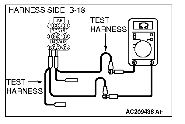
4. Measure the resistance between powertrain control module connector terminals 17 and 18.
OK: 1 kohm or more
CAUTION: Strictly observe the specified wiring harness repair procedure.
Q: Does the resistance measure 1 kohm or more?
YES:
NO:
STEP 44. Check the ASC/TCL-ECU for short circuit. Measure the resistance at ASC/TCL-ECU connector A-32.
CAUTION: A digital multimeter should be used.
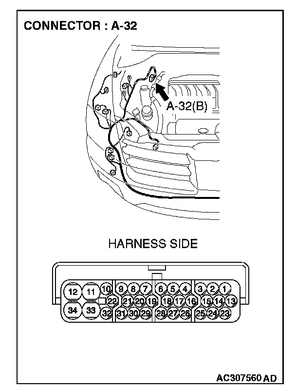
1. Disconnect ASC/TCL-ECU connector A-32, and measure the resistance at the equipment side of ASC/TCL-ECU connector A-32.
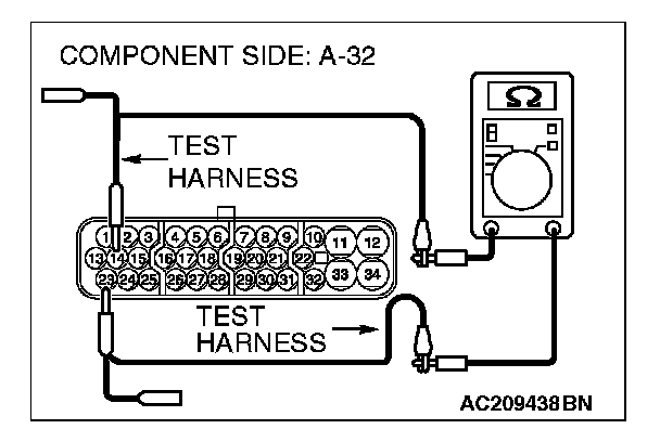
2. Measure the resistance between ASC/TCL-ECU connector terminals 14 and 23.
OK: 1 kohm or more
Q: Does the resistance measure 1 kohm or more?
YES:
NO:
STEP 45. Check the powertrain control module for short circuit. Measure the resistance at powertrain control module connector B-18.
CAUTION: A digital multimeter should be used.
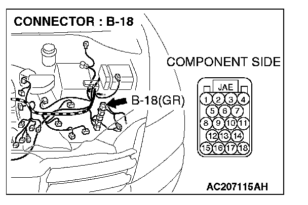
1. Disconnect powertrain control module connector B-18, and measure the resistance at the equipment side of powertrain control module connector B-18.
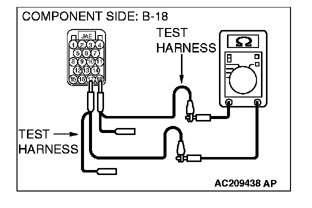
2. Measure the resistance between powertrain control module connector terminals 17 and 18.
OK: 120 ± 20 ohms
Q: Does the resistance measure 120 ± 20 ohms?
YES:
NO: