Part 2
STEP 18. Using scan tool MB991958, diagnose the CAN bus line (Disconnect TPMS receiver connector C-118, and check the supplemental restraint system).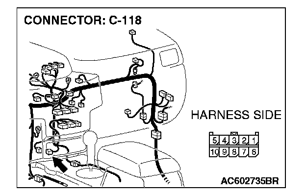
1. Disconnect TPMS receiver connector C-118.
2. Turn the ignition switch to the "ON" position.
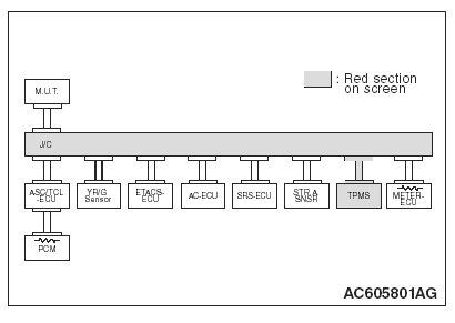
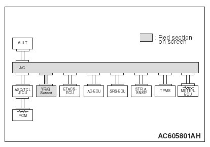
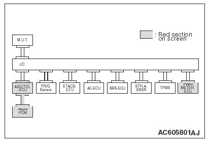
3. Diagnose CAN bus lines, and check if the M.U.T.-III screen is as shown in the illustration.
4. Turn the ignition switch to the "LOCK" (OFF) position.
5. Connect the TPMS receiver connector C-118.
Q: Does the M.U.T.-III screen correspond to the illustration?
YES: If the M.U.T.-III screen corresponds to the illustration, go to Step 19.
NO: If the M.U.T.-III screen does not correspond to the illustration, go to Step 20.
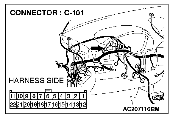
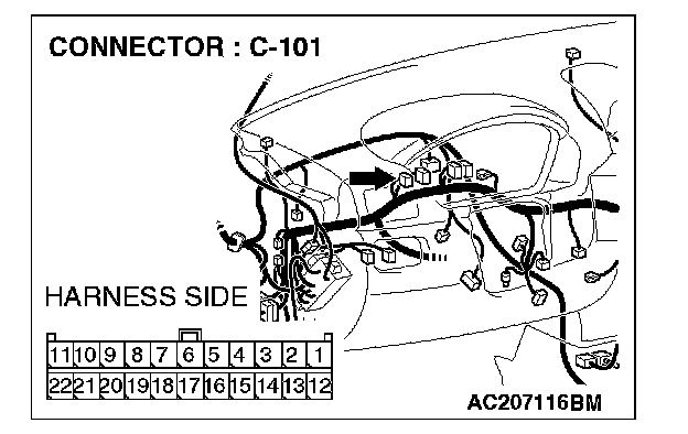
STEP 19. Check the CAN bus lines between joint connector (4) and the TPMS receiver. Measure the resistance between joint connector (4) C-101 and TPMS receiver connector C-118.
CAUTION:
- A digital multimeter should be used.
- The test wiring harness should be used.
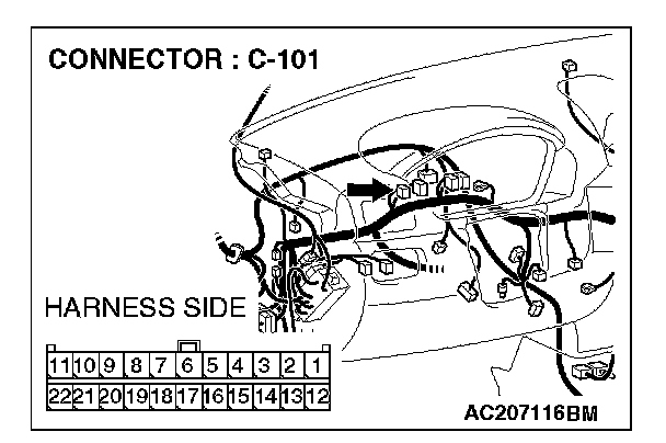

1. Disconnect joint connector (4) C-101 and TPMS receiver connector C-118 and measure the resistances at the wiring harness sides of joint connector (4) C-101 and TPMS receiver connector C-118.
2. Turn the ignition switch to the "LOCK" (OFF) position.
CAUTION: Disconnect the negative battery terminal.
3. Disconnect the negative battery terminal.
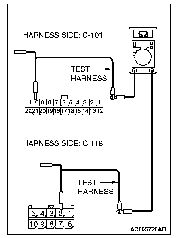
4. Measure the resistance between joint connector (4) terminal 10 and TPMS receiver connector terminal 2.
OK: 2 ohms or less
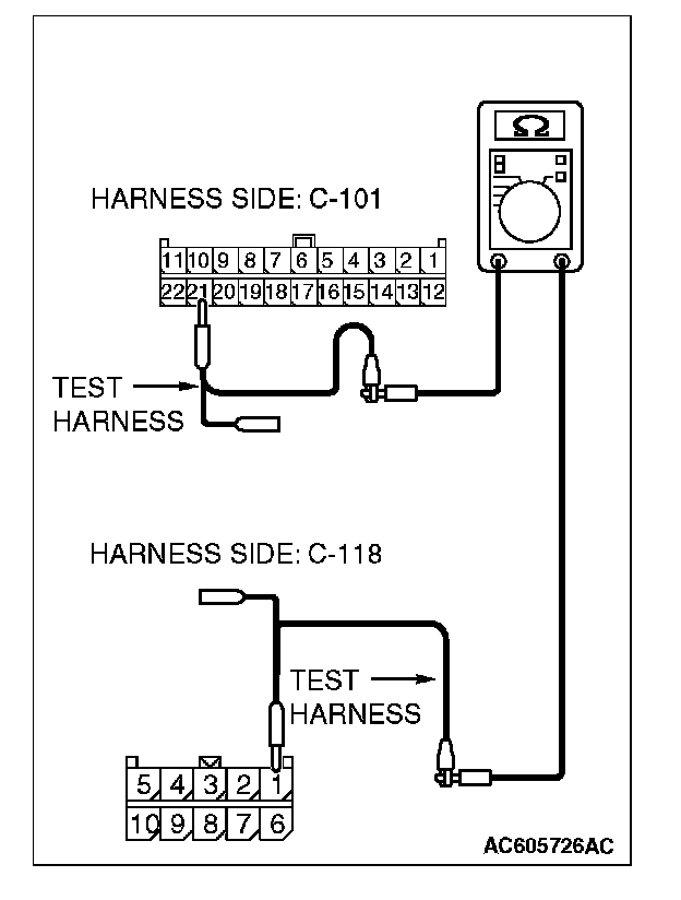
5. Measure the resistance between joint connector (4) terminal 21 and TPMS receiver connector terminal 1.
OK: 2 ohms or less
CAUTION: Strictly observe the specified wiring harness repair procedure.
Q: Do all the resistances measure 2 ohms or less?
YES: If all the resistances measure 2 ohms or less, power supply to the TPMS receiver may be suspected. Diagnose the supplemental restraint system. Refer to SRS air bag diagnosis, equipment diagnosis.
NO: If either of the resistances measures more than 2 ohms or all the resistances measure more than 2 ohms, repair the wiring harness between joint connector (4) and the TPMS receiver connector.
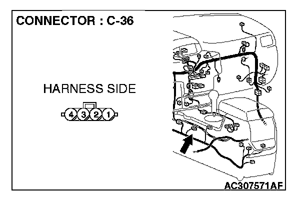
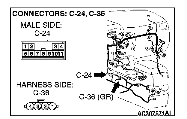
STEP 20. Check G and yaw rate sensor connector C-36 for loose, corroded or damaged terminals, or terminals pushed back in the connector.
CAUTION: The strand end of the twist wire should be within 10 cm (4 inches) from the connector.
Q: Is G and yaw rate sensor connector C-36 in good condition?
YES: Go to Step 21.
NO: Repair the damaged parts.
STEP 21. Using scan tool MB991958, diagnose the CAN bus line (Disconnect G and yaw rate sensor connector C-36, and check the G and yaw rate sensor system).
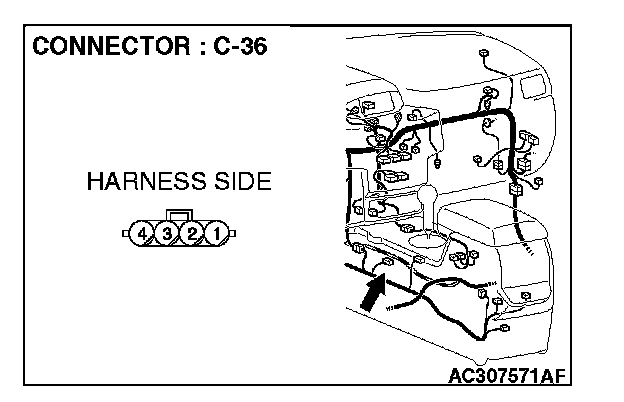
1. Disconnect G and yaw rate sensor connector C-36.
2. Turn the ignition switch to the "ON" position.
3. Diagnose CAN bus lines, and check if the M.U.T.-III screen is as shown in the illustration.
4. Turn the ignition switch to the "LOCK" (OFF) position.
5. Connect G and yaw rate sensor connector C-36.
Q: Does the M.U.T.-III screen correspond to the illustration?
YES:
NO:
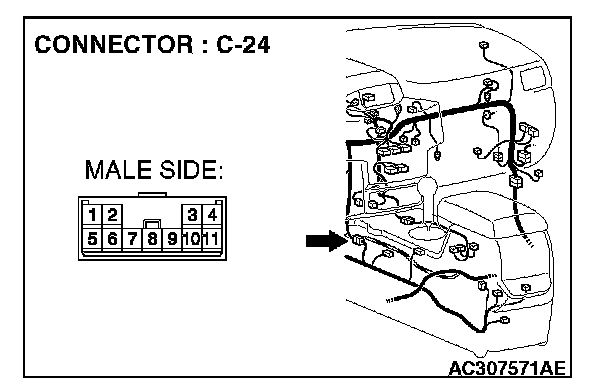
STEP 22. Check intermediate connector C-24 for loose, corroded or damaged terminals, or terminals pushed back in the connector.
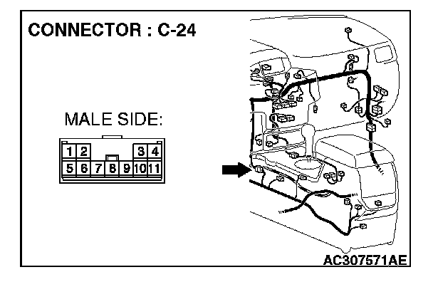
CAUTION: The strand end of the twist wire should be within 10 cm (4 inches) from the connector.
Q: Is intermediate connector C-24 in good condition?
YES: Go to Step 23.
NO: Repair the damaged parts.
STEP 23. Check the CAN bus lines between intermediate connector C-24 and the G and yaw rate sensor. Measure the resistance between intermediate connector C-24 and G and yaw rate sensor connector C-36.
CAUTION:
- A digital multimeter should be used.
- The test wiring harness should be used.
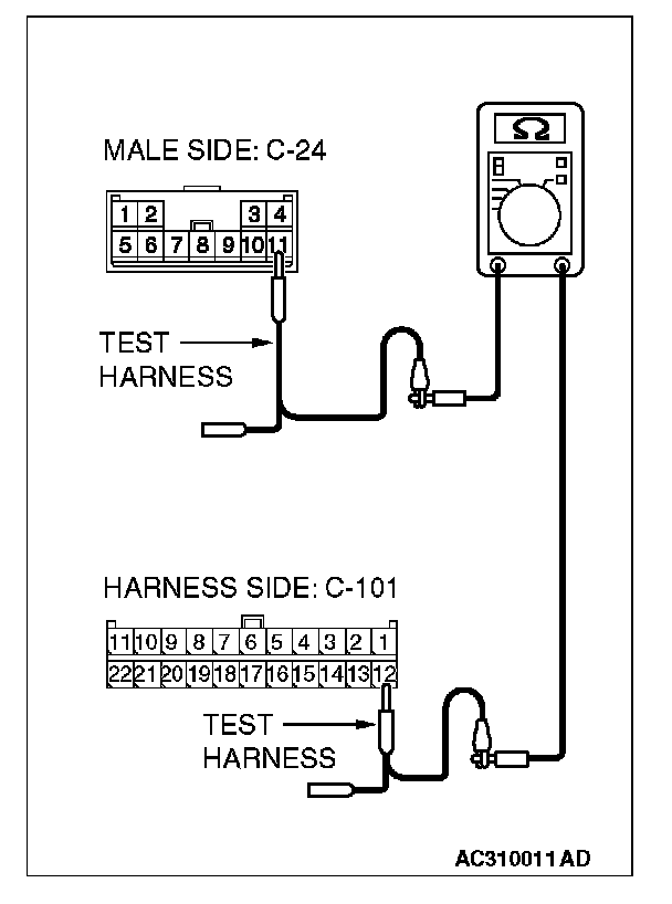
1. Disconnect intermediate connector C-24 and G and yaw rate sensor connector C-36, and measure the resistance between the wiring harness side connector of G and yaw rate sensor connector C-36 and the male side connector of intermediate connector C-24 (at front wiring harness side).
2. Turn the ignition switch to the "LOCK" (OFF) position.
CAUTION: Disconnect the negative battery terminal.
3. Disconnect the negative battery terminal.
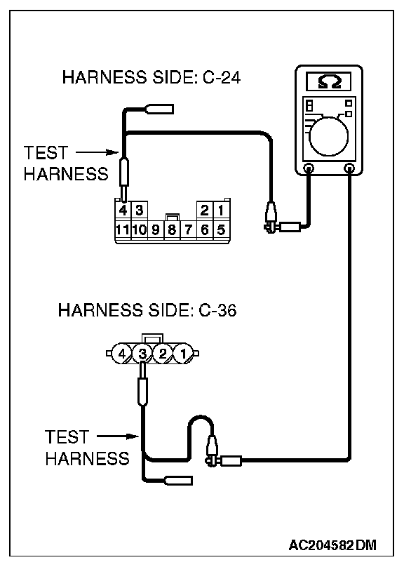
4. Measure the resistance between intermediate connector terminal 4 and G and yaw rate sensor connector terminal 3.
OK: 2 ohms or less
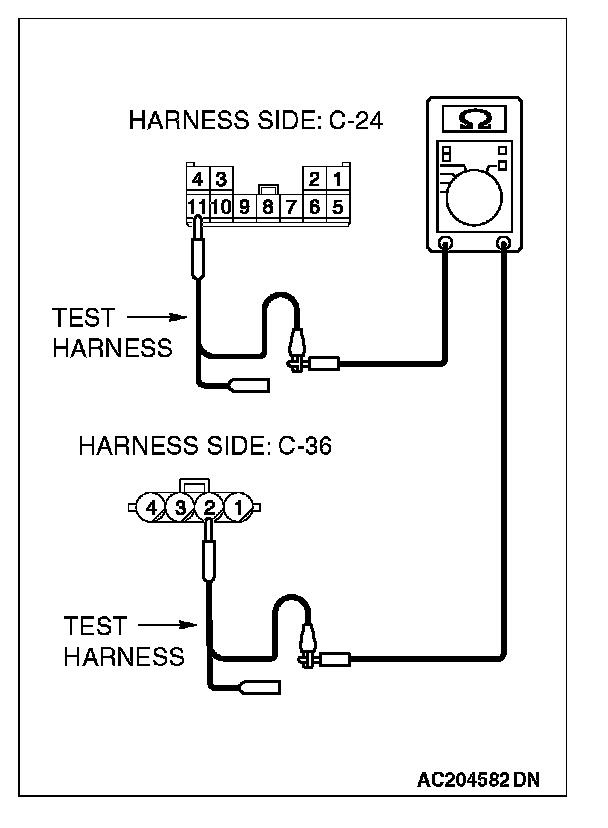
5. Measure the resistance between intermediate connector terminal 11 and G and yaw rate sensor connector terminal 2.
OK: 2 ohms or less
CAUTION: Strictly observe the specified wiring harness repair procedure.
Q: Do all the resistances measure 2 ohms or less?
YES:
NO:
STEP 24. Check the CAN bus lines between intermediate connector C-24 and the joint connector (4). Measure the resistance between intermediate connector C-24 and joint connector (4) C-101.
CAUTION:
- A digital multimeter should be used.
- The test wiring harness should be used.
1. Disconnect joint connector (4) C-101 and intermediate connector C-24, and measure the resistance between the wiring harness side connector of joint connector (4) C-101and the female side connector of intermediate connector C-24 (instrument panel wiring harness side).
2. Turn the ignition switch to the "LOCK" (OFF) position.
CAUTION: Disconnect the negative battery terminal.
3. Disconnect the negative battery terminal.
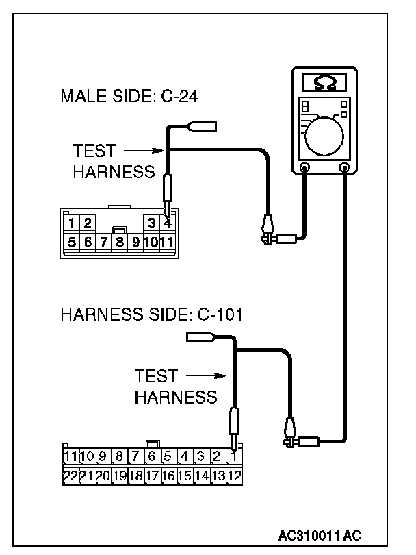
4. Measure the resistance between joint connector (4) terminal 1 and intermediate connector terminal 4.
OK: 2 ohms or less
5. Measure the resistance between joint connector (4) terminal 12 and intermediate connector terminal 11.
OK: 2 ohms or less
CAUTION: Strictly observe the specified wiring harness repair procedure.
Q: Do all the resistances measure 2 ohms or less?
YES:
NO:
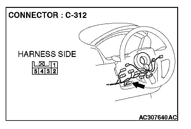
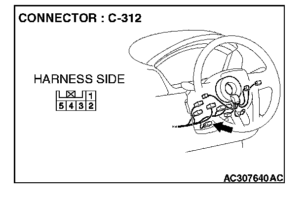
STEP 25. Check steering wheel sensor connector C-312 for loose, corroded or damaged terminals, or terminals pushed back in the connector.
CAUTION: The strand end of the twist wire should be within 10 cm (4 inches) from the connector.
Q: Is steering wheel sensor connector C-312 in good condition?
YES: Go to Step 26.
NO: Repair the damaged parts.
STEP 26. Using scan tool MB991958, diagnose the CAN bus line (Disconnect steering wheel sensor connector C-312, and check the steering wheel sensor system).
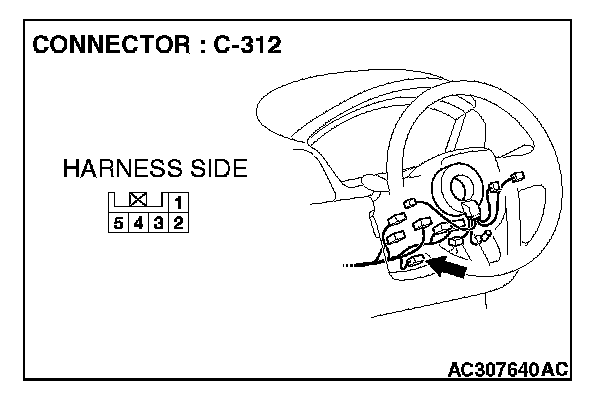
1. Disconnect steering wheel sensor connector C-312.
2. Turn the ignition switch to the "ON" position.
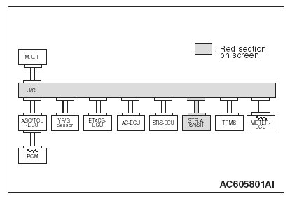
3. Diagnose CAN bus lines, and check if the M.U.T.-III screen is as shown in the illustration.
4. Turn the ignition switch to the "LOCK" (OFF) position.
5. Connect steering wheel sensor connector C-312.
Q: Does the M.U.T.-III screen correspond to the illustration?
YES:
NO:
STEP 27. Check the CAN bus lines between joint connector (4) and the steering wheel sensor. Measure the resistance between joint connector (4) C-101 and steering wheel sensor connector C-312.
CAUTION:
- A digital multimeter should be used.
- The test wiring harness should be used.
1. Disconnect joint connector (4) C-101 and steering wheel sensor connector C-312, and measure the resistance between each wiring harness side connector.
2. Turn the ignition switch to the "LOCK" (OFF) position.
CAUTION: Disconnect the negative battery terminal.
3. Disconnect the negative battery terminal.
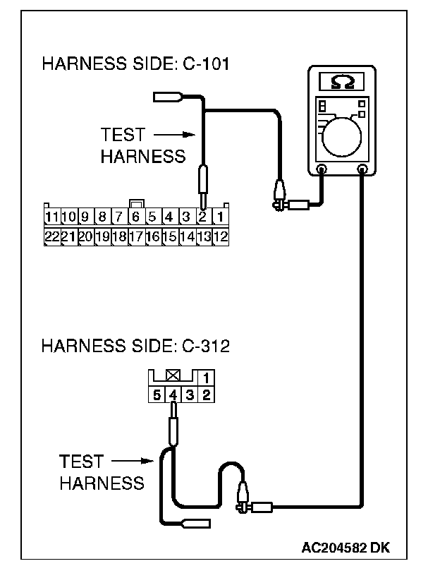
4. Measure the resistance between joint connector (4) terminal 2 and steering wheel sensor connector terminal 4.
OK: 2 ohms or less
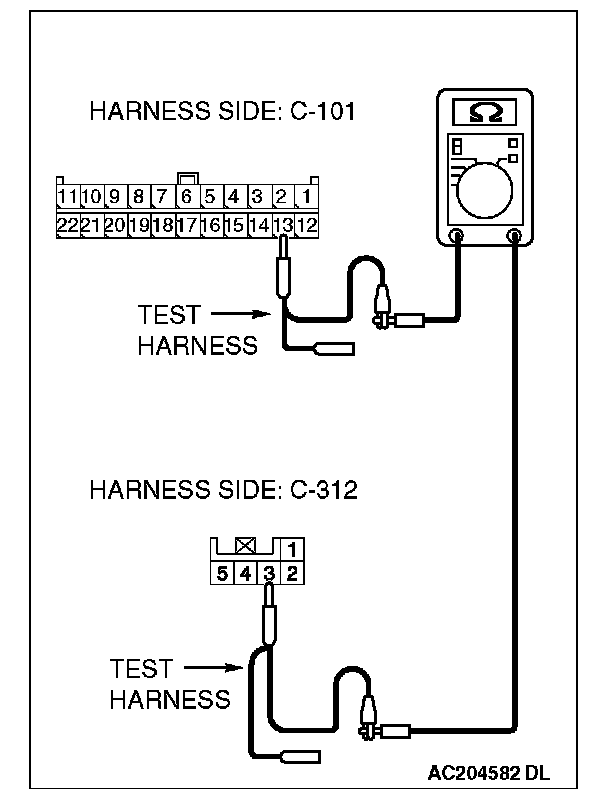
5. Measure the resistance between joint connector (4) terminal 13 and steering wheel sensor connector terminal 3.
OK: 2 ohms or less
CAUTION: Strictly observe the specified wiring harness repair procedure.
Q: Do all the resistances measure 2 ohms or less?
YES:
NO:
STEP 28. Check the CAN bus lines between joint connector (4) and the data link connector. Measure the resistance between joint connector (4) C-101 and data link connector C-121.
CAUTION:
- A digital multimeter should be used.
- The test wiring harness should be used.
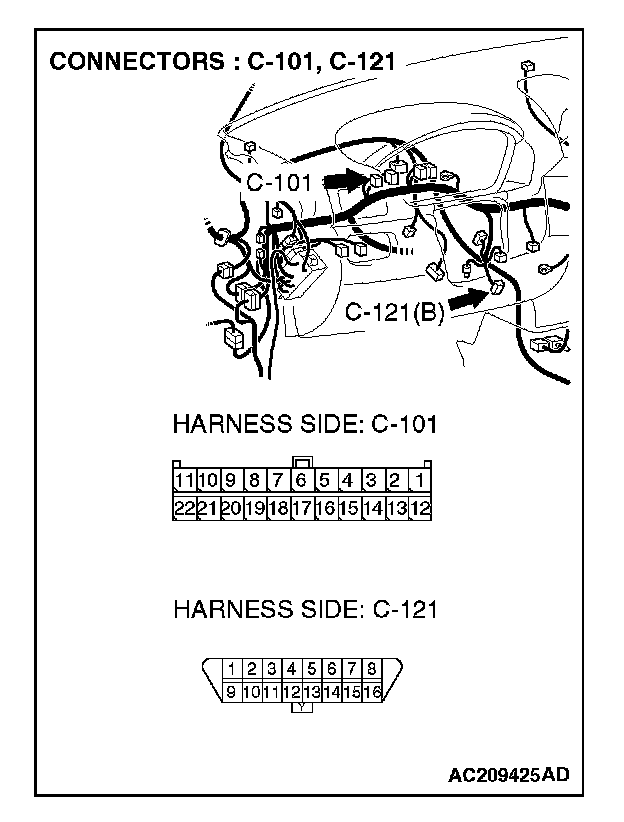
1. Disconnect joint connector (4) C-101, and measure the resistance between the wiring harness side connector of joint connector (4) C-101 and wiring harness side connector of data link connector C-121.
2. Turn the ignition switch to the "LOCK" (OFF) position.
CAUTION: Disconnect the negative battery terminal.
3. Disconnect the negative battery terminal.
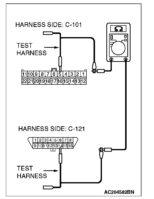
4. Measure the resistance between joint connector (4) terminal 5 and data link connector terminal 14.
OK: 2 ohms or less
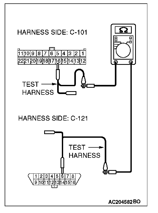
5. Measure the resistance between joint connector (4) terminal 16 and data link connector terminal 6.
OK: 2 ohms or less
CAUTION: Strictly observe the specified wiring harness repair procedure.
Q: Do all the resistances measure 2 ohms or less?
YES:
NO:
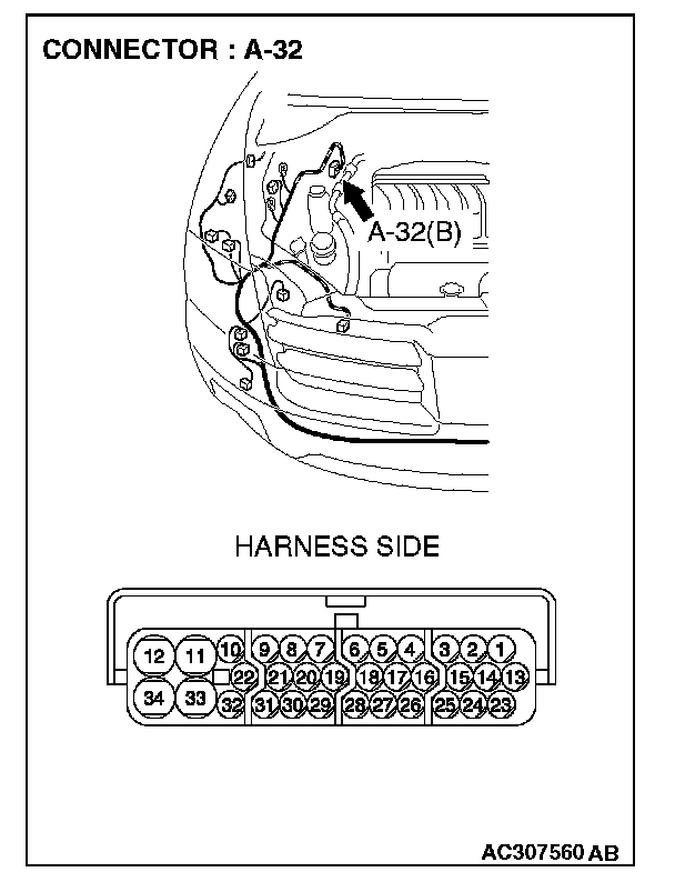
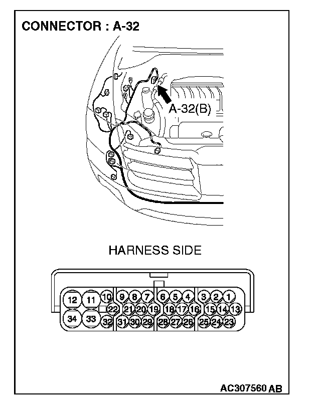
STEP 29. Check ASC/TCL-ECU connector A-32 and powertrain control module connector B-18 for loose, corroded or damaged terminals, or terminals pushed back in the connector.
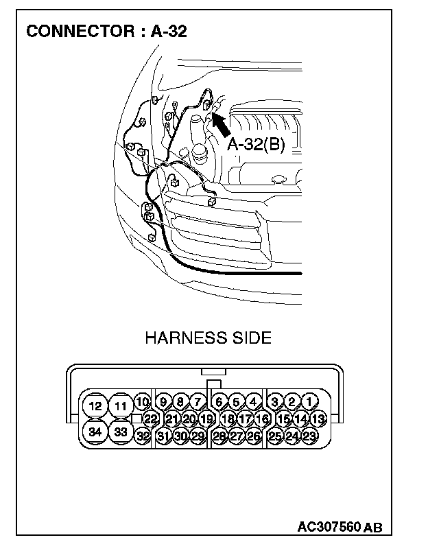
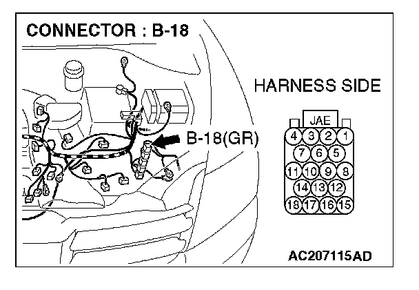
CAUTION: The strand end of the twist wire should be within 10 cm (4 inches) from the connector.
Q: Are ASC/TCL-ECU connector A-32 and powertrain control module connector B-18 in good condition?
YES: Go to Step 30.
NO: Repair the damaged parts.
STEP 30. Using scan tool MB991958, diagnose the CAN bus line (Disconnect powertrain control module connector B-18, and check the powertrain control module system).
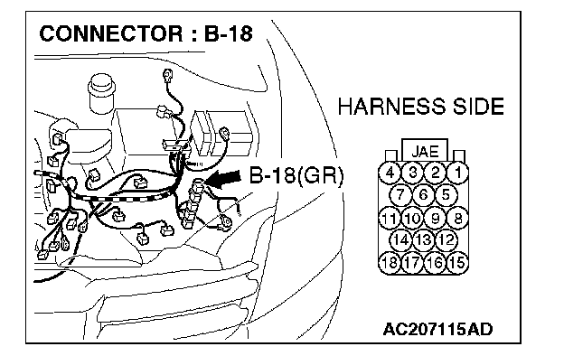
1. Disconnect powertrain control module connector B-18.
2. Turn the ignition switch to the "ON" position.
3. Diagnose CAN bus lines, and check if the M.U.T.-III screen is as shown in the illustration.
4. Turn the ignition switch to the "LOCK" (OFF) position.
5. Connect powertrain control module connector B-18.
Q: Does the M.U.T.-III screen correspond to the illustration?
YES:
NO:
STEP 31. Check the CAN bus lines between the ASC/TCL-ECU and the powertrain control module. Measure the resistance between ASC/TCL-ECU connector A-32 and powertrain control module connector B-18.
CAUTION:
- A digital multimeter should be used.
- The test wiring harness should be used.
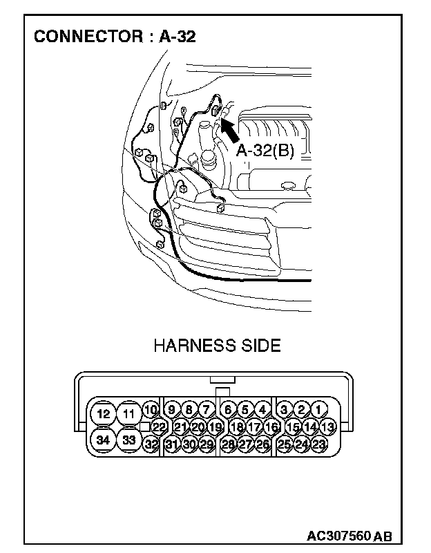
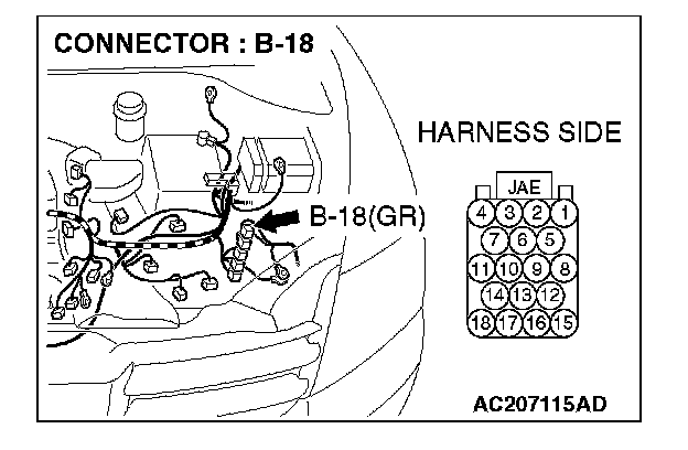
1. Disconnect ASC/TCL-ECU connector A-32 and powertrain control module connector B-18, and measure the resistance between each wiring harness side connector.
2. Turn the ignition switch to the "LOCK" (OFF) position.
CAUTION: Disconnect the negative battery terminal.
3. Disconnect the negative battery terminal.
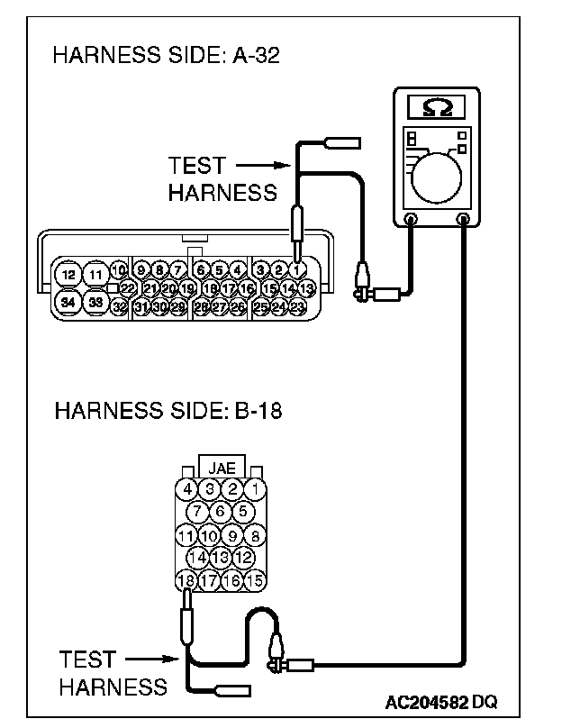
4. Measure the resistance between ASC/TCL-ECU connector terminal 1 and powertrain control module connector terminal 18.
OK: 2 ohms or less
5. Measure the resistance between ASC/TCL-ECU connector terminal 13 and powertrain control module connector terminal 17.
OK: 2 ohms or less
CAUTION: Strictly observe the specified wiring harness repair procedure.
Q: Do all the resistances measure 2 ohms or less?
YES:
NO:
STEP 32. Check the CAN bus lines inside the ASC/TCL-ECU. Measure the resistance at ASC/TCL-ECU connector A-32.
CAUTION:
- A digital multimeter should be used.
- The test wiring harness should be used.
1. Disconnect ASC/TCL-ECU connector A-32, and measure the resistance at the equipment side of ASC/TCL-ECU connector A-32.
2. Turn the ignition switch to the "LOCK" (OFF) position.
CAUTION: Disconnect the negative battery terminal.
3. Disconnect the negative battery terminal.
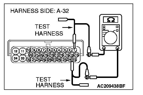
4. Measure the resistance between ASC/TCL-ECU connector terminals 1 and 14.
OK: 2 ohms or less
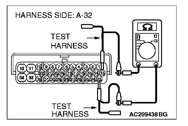
5. Measure the resistance between ASC/TCL-ECU connector terminals 13 and 23.
OK: 2 ohms or less
CAUTION: Strictly observe the specified wiring harness repair procedure.
Q: Do all the resistances measure 2 ohms or less?
YES:
NO:
STEP 33. Using scan tool MB991958, diagnose the CAN bus line (Disconnect ASC/TCL-ECU connector A-32, and check the ASC/TCL-ECU system).

1. Disconnect ASC/TCL-ECU connector A-32.
2. Turn the ignition switch to the "ON" position.
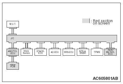
3. Diagnose CAN bus lines, and check if the M.U.T.-III screen is as shown in the illustration.
4. Turn the ignition switch to the "LOCK" (OFF) position.
5. Check ASC/TCL-ECU connector A-32.
Q: Does the M.U.T.-III screen correspond to the illustration?
YES:
NO:
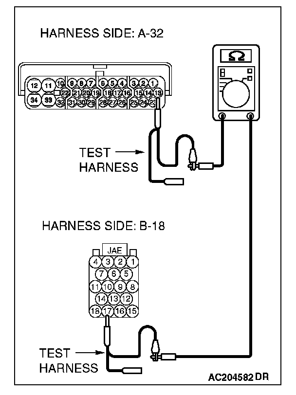
STEP 34. Check the CAN bus lines between intermediate connector C-31 and the ASC/TCL-ECU. Measure the resistance between intermediate connector C-31 and ASC/TCL-ECU connector A-32.
CAUTION:
- A digital multimeter should be used.
- The test wiring harness should be used.
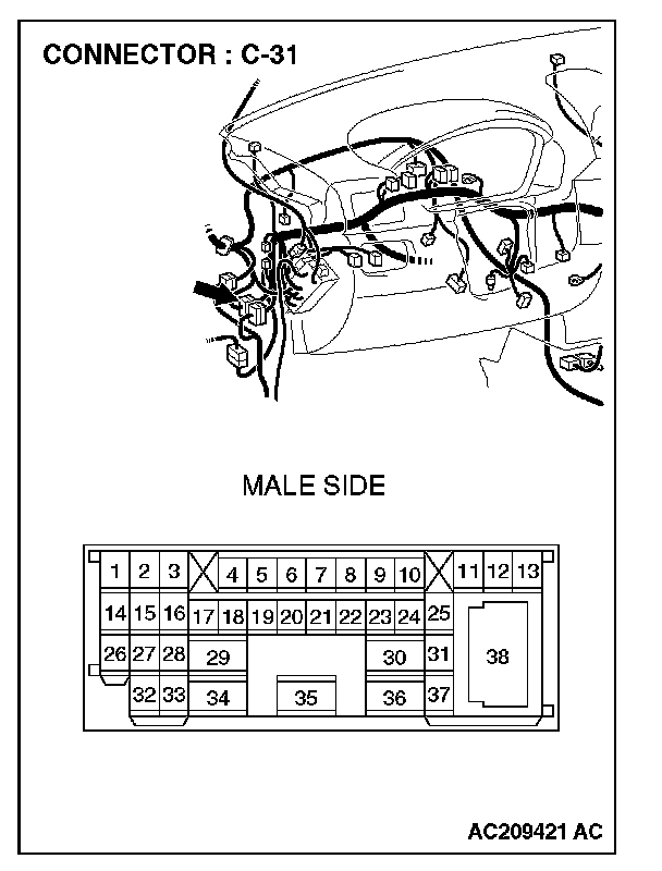
1. Disconnect intermediate connector C-31 and ASC/TCL-ECU connector A-32, and measure the resistance between the wiring harness side connector of ASC/TCL-ECU connector A-32 and the male side connector of intermediate connector C-31 (at front wiring harness side).
2. Turn the ignition switch to the "LOCK" (OFF) position.
CAUTION: Disconnect the negative battery terminal.
3. Disconnect the negative battery terminal.
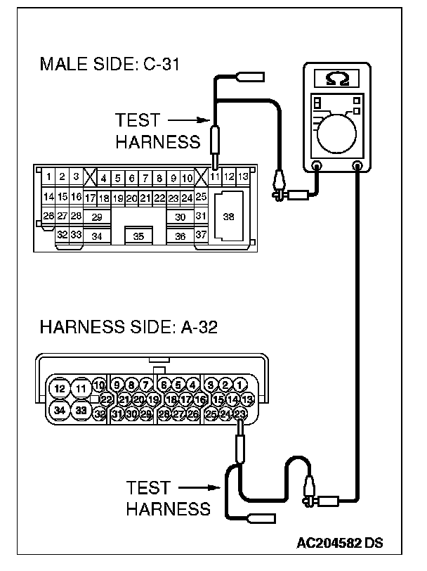
4. Measure the resistance between intermediate connector terminal 11 and ASC/TCL-ECU connector terminal 23.
OK: 2 ohms or less
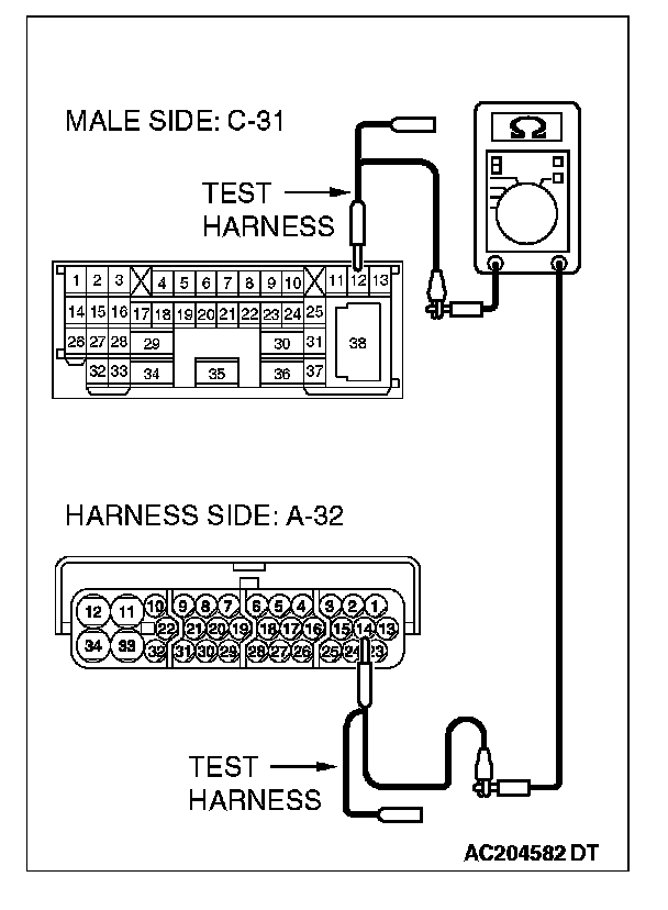
5. Measure the resistance between intermediate connector terminal 12 and ASC/TCL-ECU connector terminal 14.
OK: 2 ohms or less
CAUTION: Strictly observe the specified wiring harness repair procedure.
Q: Do all the resistances measure 2 ohms or less?
YES:
NO:
STEP 35. Check the CAN bus lines between intermediate connector C-31 and the joint connector (4). Measure the resistance between intermediate connector C-31 and joint connector (4) C-101.
CAUTION:
- A digital multimeter should be used.
- The test wiring harness should be used.
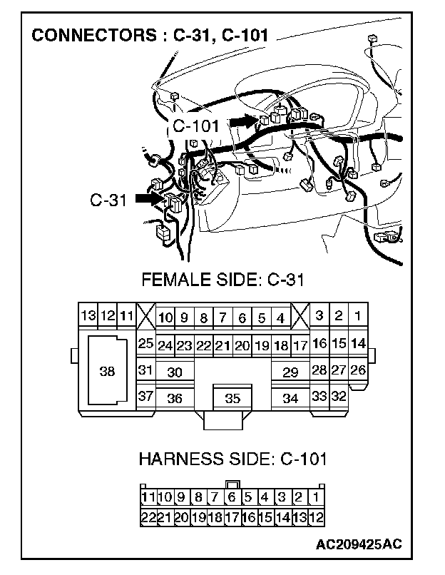
1. Disconnect joint connector (4) C-101 and intermediate connector C-31, and measure the resistance between the wiring harness side connector of joint connector (4) C-101and the female side connector of intermediate connector C-31 (instrument panel wiring harness side).
2. Turn the ignition switch to the "LOCK" (OFF) position.
CAUTION: Disconnect the negative battery terminal.
3. Disconnect the negative battery terminal.
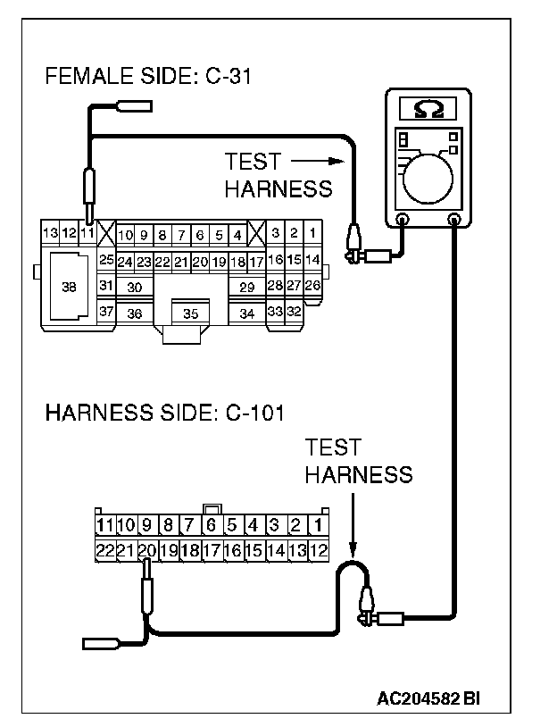
4. Measure the resistance between joint connector (4) terminal 20 and intermediate connector terminal 11.
OK: 2 ohms or less
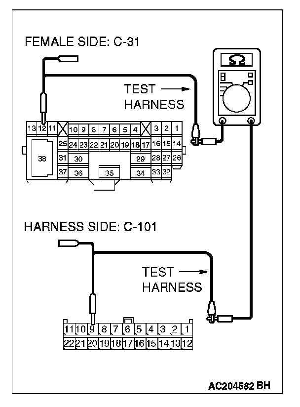
5. Measure the resistance between joint connector (4) terminal 9 and intermediate connector terminal 12.
OK: 2 ohms or less
CAUTION: Strictly observe the specified wiring harness repair procedure.
Q: Do all the resistances measure 2 ohms or less?
YES:
NO: