Diagnostic Item 21
DIAGNOSTIC ITEM 21: Diagnose the lines between CAN main bus line and the powertrain control modulePart 1:
Part 2:
CAUTION: When servicing a CAN bus line, ground yourself by touching a metal object such as an unpainted water pipe. If you fail to do so, a component connected to the CAN bus line may be damaged.
TROUBLE JUDGMENT
If the M.U.T.-III cannot received signals from the powertrain control module, CAN bus line connector(s) are broken or an open circuit has occurred.
COMMENTS ON TROUBLE SYMPTOM
The wiring harness wire or connectors may have loose, corroded, or damage terminals, or terminals pushed back in the connector, or the powertrain control module may be defective.
TROUBLESHOOTING HINTS
- The wiring harness or connectors may have loose, corroded, or damage terminals, or terminals pushed back in the connector
- The powertrain control module may be defective
- The ABS/TCL-ECU may be defective
DIAGNOSIS
Required Special Tools:
- MB991223: Harness Set
- MB992006: Extra Fine Probe
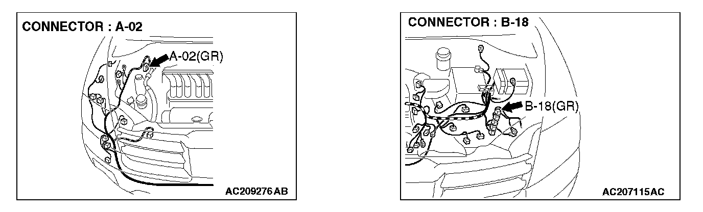
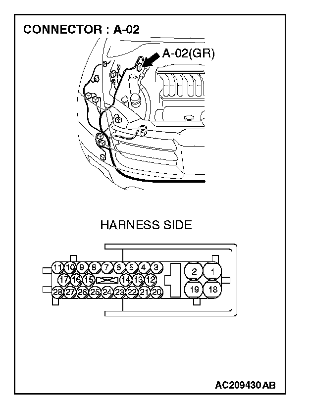
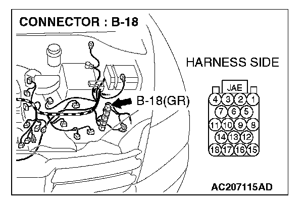
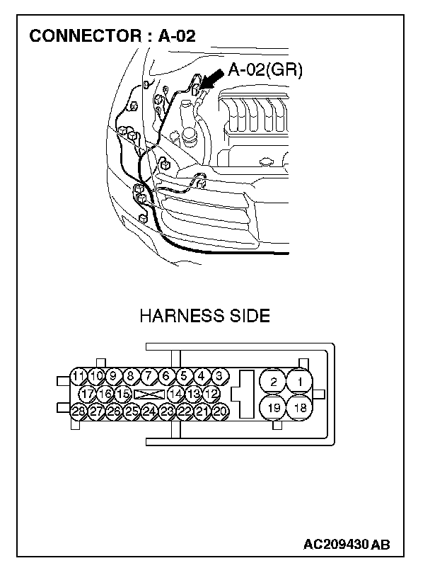
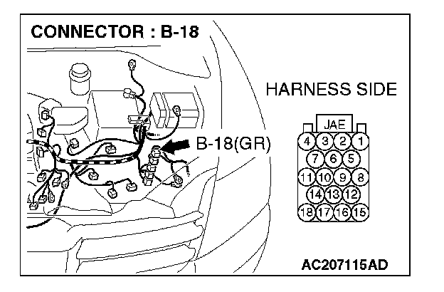
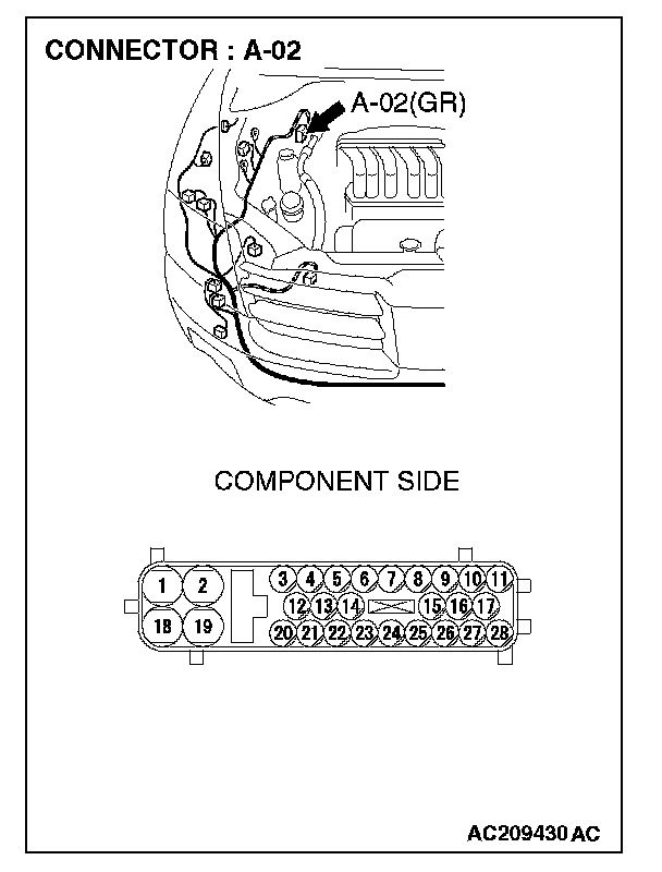
STEP 1. Check ABS/TCL-ECU connector A-02 and powertrain control module connector B-18 for loose, corroded or damaged terminals, or terminals pushed back in the connector.
CAUTION: The strand end of the twist wire should be within 10 cm (4 inches) from the connector.
Q: Are ABS/TCL-ECU connector A-02 and powertrain control module connector B-18 in good condition?
YES: Go to Step 2.
NO: Repair the damaged parts.
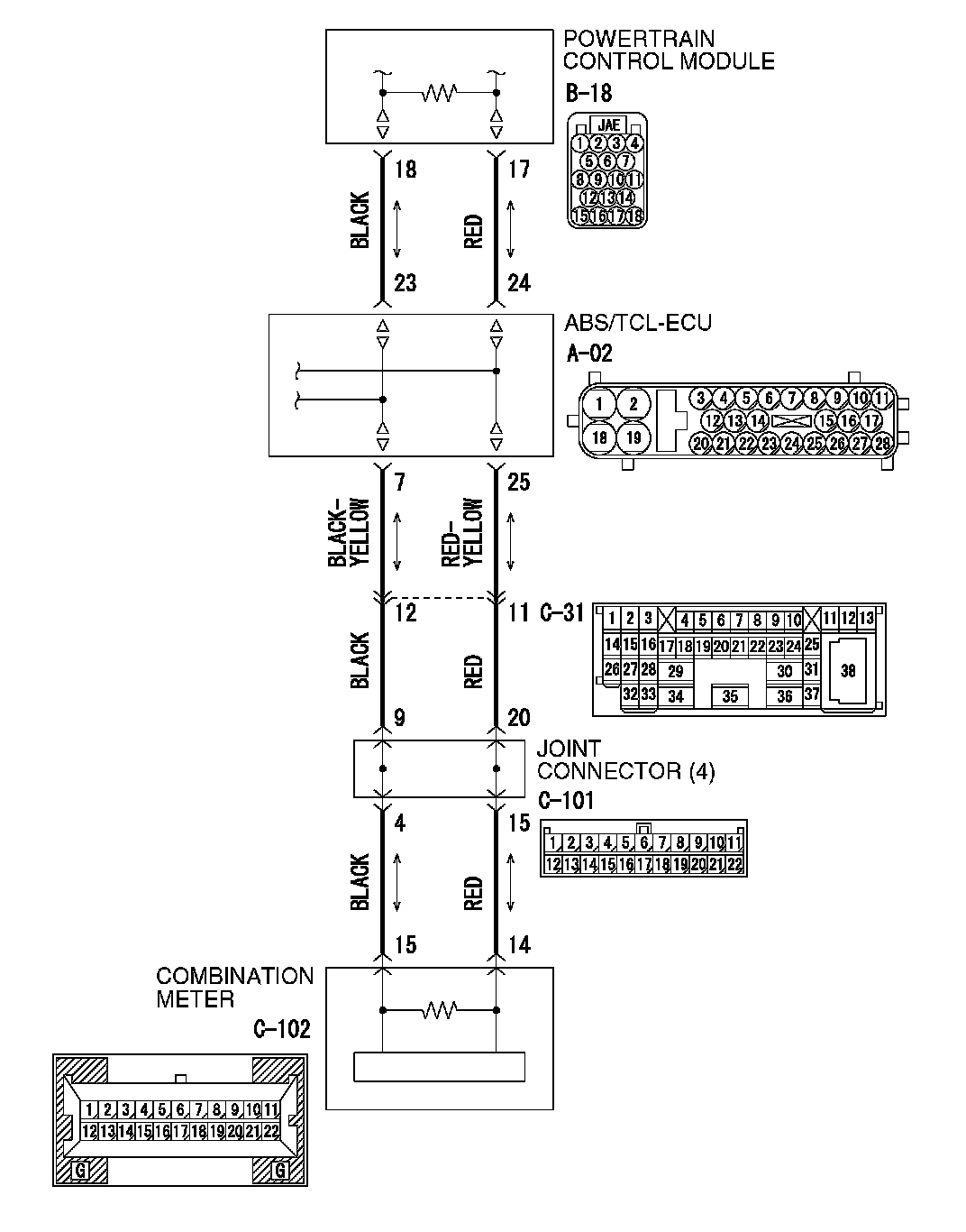
STEP 2. Check the CAN bus lines between the ABS/TCL-ECU and the powertrain control module. Measure the resistance between ABS/TCL-ECU connector A-02 and powertrain control module connector B-18.
CAUTION:
- A digital multimeter should be used.
- The test wiring harness should be used.
1. Disconnect ABS/TCL-ECU connector A-02 and powertrain control module connector B-18, and measure the resistance between each wiring harness side connector.
2. Turn the ignition switch to the "LOCK" (OFF) position.
CAUTION: Disconnect the negative battery terminal.
3. Disconnect the negative battery terminal.
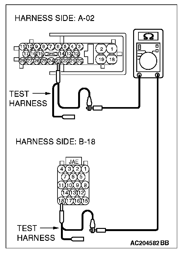
4. Measure the resistance between ABS/TCL-ECU connector terminal 23 and powertrain control module connector terminal 18.
OK: 2 ohms or less
5. Measure the resistance between ABS/TCL-ECU connector terminal 24 and powertrain control module connector terminal 17.
OK: 2 ohms or less
CAUTION: Strictly observe the specified wiring harness repair procedure.
Q: Do all the resistances measure 2 ohms or less?
YES:
NO:
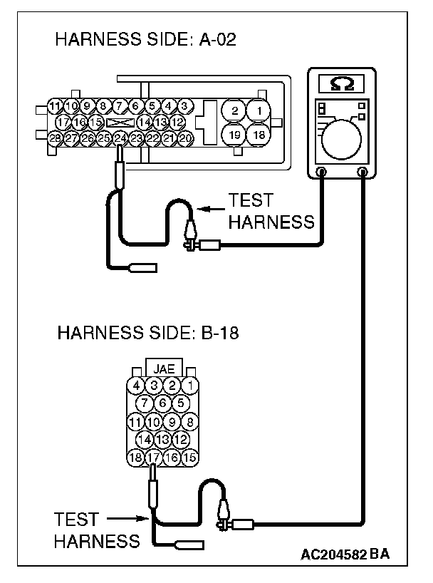
STEP 3. Check the CAN bus lines inside the ABS/TCL-ECU. Measure the resistance at ABS/TCL-ECU connector A-02.
CAUTION:
- A digital multimeter should be used.
- The test wiring harness should be used.
1. Disconnect ABS/TCL-ECU connector A-02, and measure the resistance at the equipment side of ABS/TCL-ECU connector A-02.
2. Turn the ignition switch to the "LOCK" (OFF) position.
CAUTION: Disconnect the negative battery terminal.
3. Disconnect the negative battery terminal.
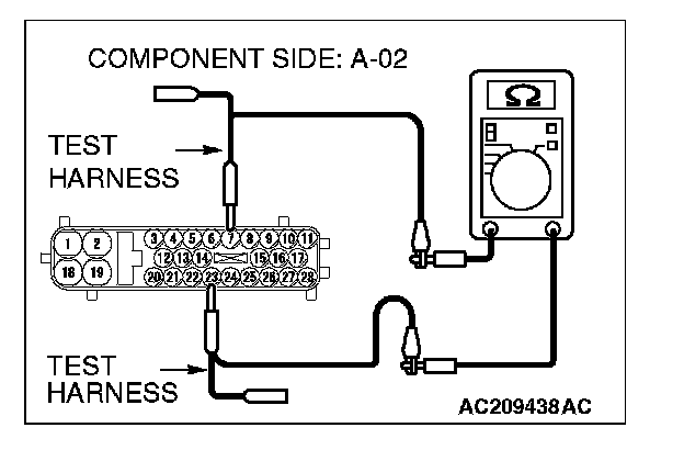
4. Measure the resistance between ABS/TCL-ECU connector terminals 7 and 23.
OK: 2 ohms or less
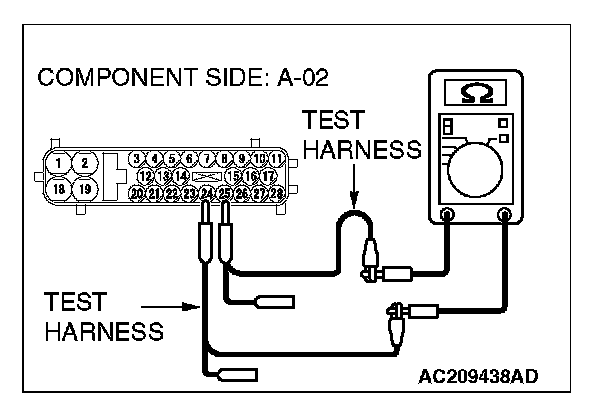
5. Measure the resistance between ABS/TCL-ECU connector terminals 24 and 25.
OK: 2 ohms or less
CAUTION: Strictly observe the specified wiring harness repair procedure.
Q: Do all the resistances measure 2 ohms or less?
YES:
NO: