Part 1
DIAGNOSTIC ITEM 4: Diagnose shorts in the power supply to CAN bus linePart 1:
Part 2:
Part 3:
CAUTION: When servicing a CAN bus line, ground yourself by touching a metal object such as an unpainted water pipe. If you fail to do so, a component connected to the CAN bus line may be damaged.
TROUBLE JUDGMENT
A short to the power supply may be present when the voltage between the CAN bus line (CAN_L or CAN_H) and body ground is more than 4.0 V. In this condition, an abnormal voltage may be measured at CAN_L and CAN_H lines.
COMMENTS ON TROUBLE SYMPTOM
The wiring harness wire or connectors may have loose, corroded, or damage terminals, or terminals pushed back in the connector, or an ECU may be defective.
TROUBLESHOOTING HINTS
- The wiring harness or connectors may have loose, corroded, or damaged terminals, or terminals pushed back in the connector
- The ETACS-ECU may be defective
- The SRS-ECU may be defective
- The combination meter may be defective
- The A/C-ECU may be defective
- The G and yaw rate sensor may be defective
- The steering wheel sensor may be defective
- The TPMS receiver may be defective
- The multi-center display unit (middle-grade type or vehicles with Mitsubishi multi communication system) may be defective
- The ASC/TCL-ECU may be defective
- The powertrain control module may be defective
DIAGNOSIS
Required Special Tools:
- MB991223: Harness Set
- MB992006: Extra Fine Probe
- MB991952: ABS Check Harness
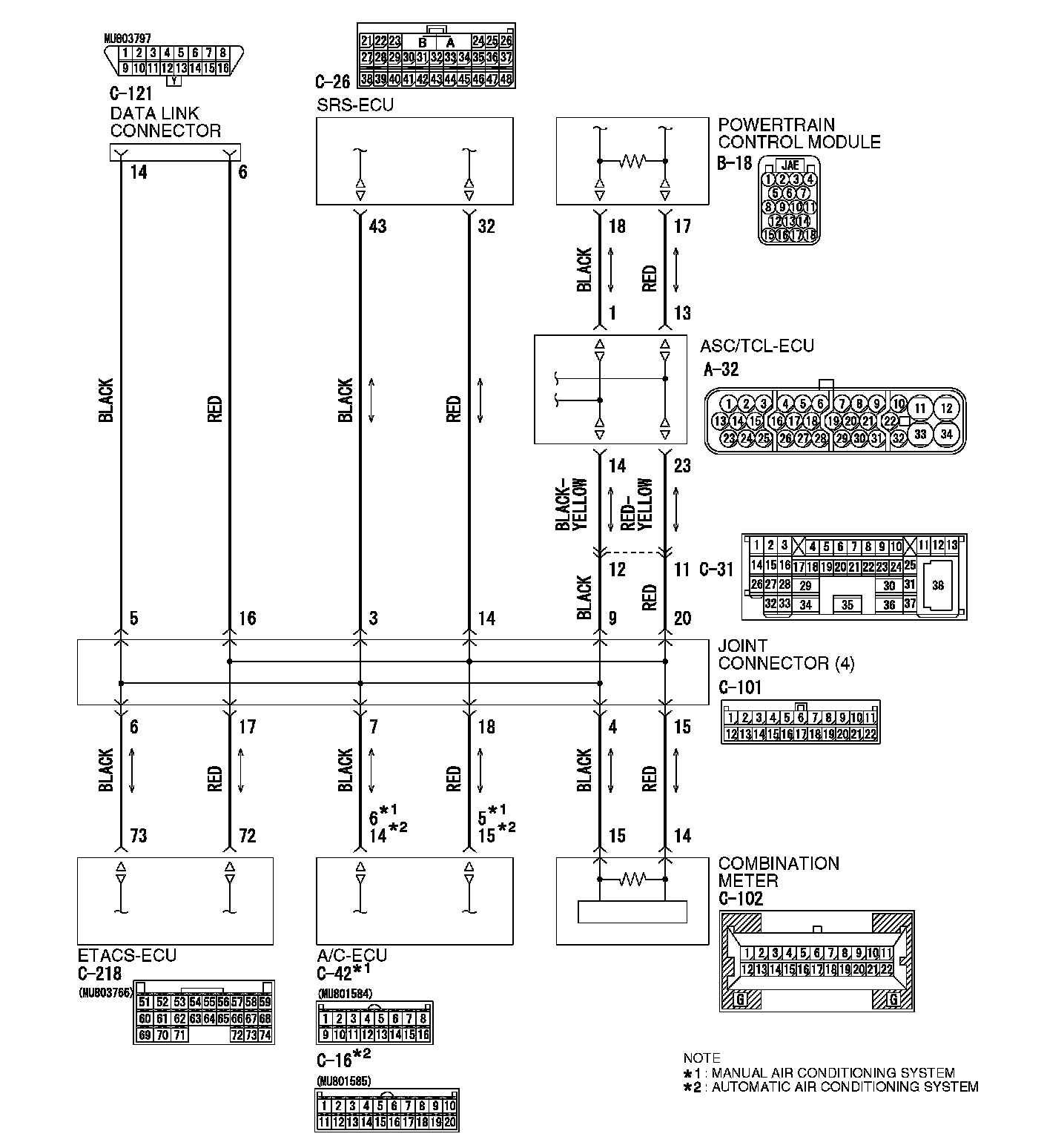
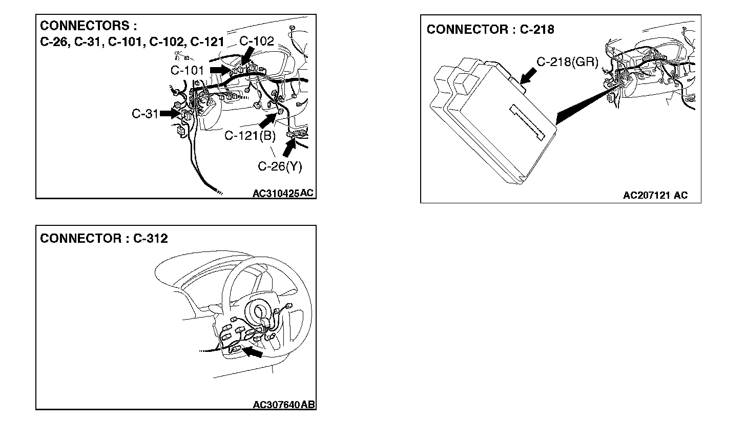
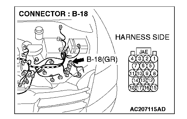
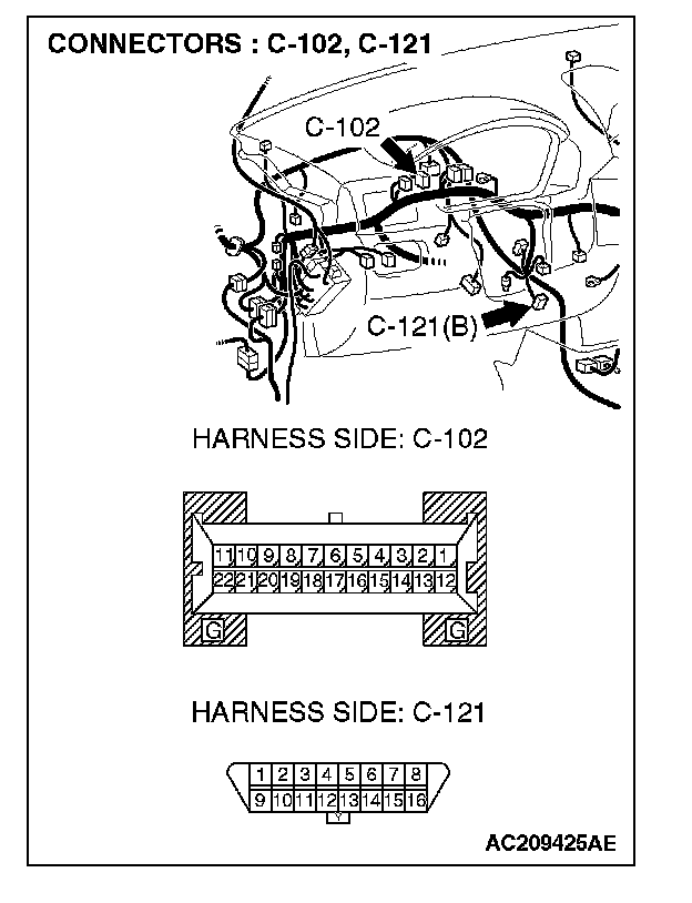
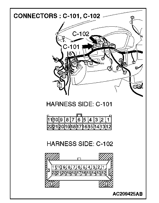
STEP 1. Check powertrain control module connector B-18, combination meter connector C-102 and data link connector C-121 for loose, corroded or damaged terminals, or terminals pushed back in the connector.
CAUTION: The strand end of the twist wire should be within 10 cm (4 inches) from the connector.
Q: Are powertrain control module connector B-18, combination meter connector C-102 and data link connector C-121 in good condition?
YES: Go to Step 2.
NO: Repair the damaged parts.
STEP 2. Check the CAN_H-side bus line (communication line including ECUs) for a short to the power supply.Measure the voltage at data link connector C-121.
CAUTION:
- A digital multimeter should be used.
- The test wiring harness should be used.
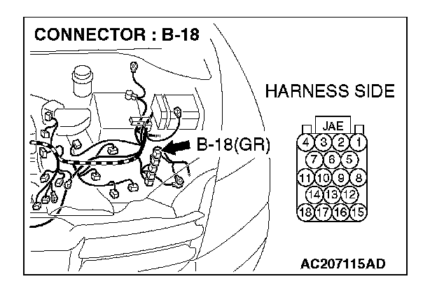
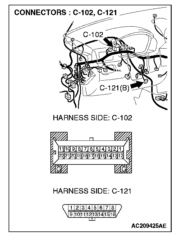
1. Disconnect powertrain control module connector B-18 and combination meter connector C-102, and measure the voltage at the harness side of data link connector C-121.
2. Turn the ignition switch to the "ON" position.
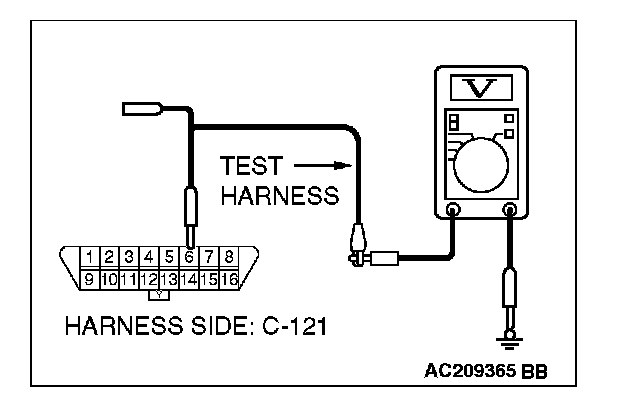
3. Measure the voltage between data link connector terminal 6 and body ground.
OK: 4.0 V or less
Q: Does the voltage measure 4.0 V or less?
YES:
NO:
STEP 3. Check the CAN_L-side bus line (communication line including ECUs) for a short to the power supply. Measure the voltage at data link connector C-121.
CAUTION:
- A digital multimeter should be used.
- The test wiring harness should be used.
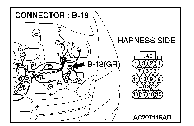

1. Disconnect powertrain control module connector B-18 and combination meter connector C-102, and measure the voltage at the harness side of data link connector C-121.
2. Turn the ignition switch to the "ON" position.
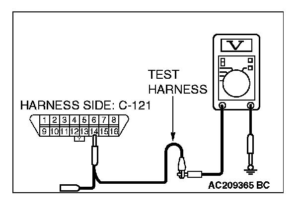
3. Measure the voltage between data link connector terminal 14 and body ground.
OK: 4.0 V or less
Q: Does the voltage measure 4.0 V or less?
YES:
NO:
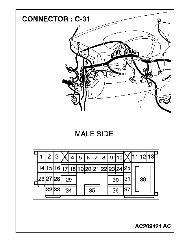
STEP 4. Check intermediate connector C-31 for loose, corroded or damaged terminals, or terminals pushed back in the connector.
CAUTION: The strand end of the twist wire should be within 10 cm (4 inches) from the connector.
Q: Is intermediate connector C-31 in good condition?
YES: Go to Step 5 .
NO: Repair the damaged parts.
STEP 5. Check the CAN_H-side bus line (communication line including ECUs) of the front wiring harness for a short to the power supply. Measure the voltage at intermediate connector C-31.
CAUTION:
- A digital multimeter should be used.
- The test wiring harness should be used.
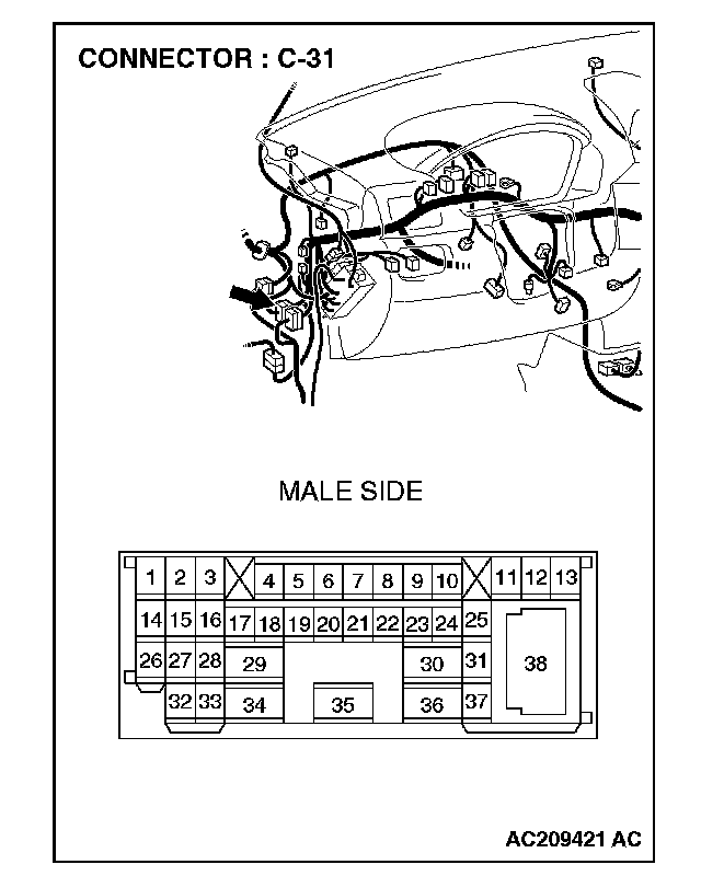
1. Disconnect intermediate connector C-31, and measure the voltage at the male side (at front wiring harness side).
2. Turn the ignition switch to the "ON" position.
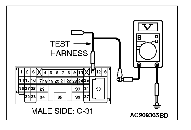
3. Measure the voltage between intermediate connector C-31 terminal 11 and body ground.
OK: 4.0 V or less
Q: Does the voltage measure 4.0 V or less?
YES:
NO:
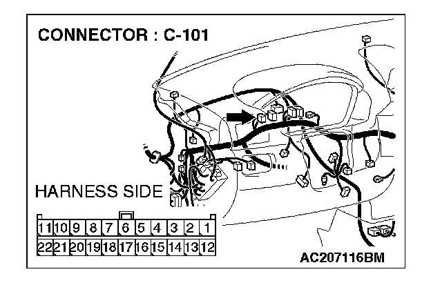
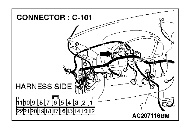
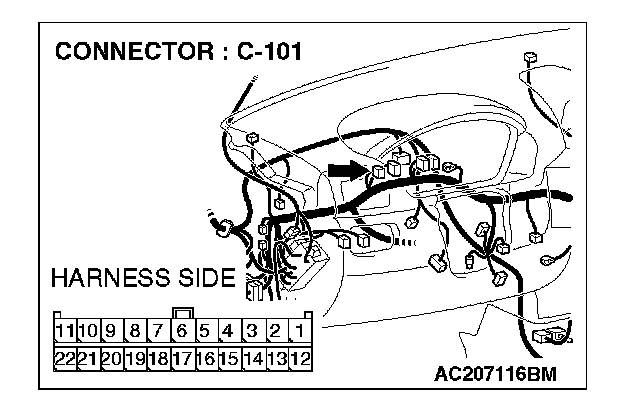
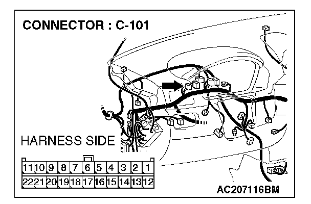
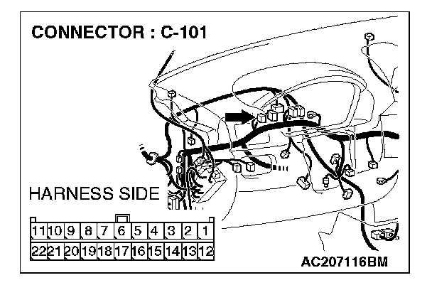
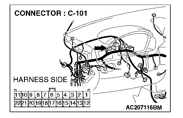
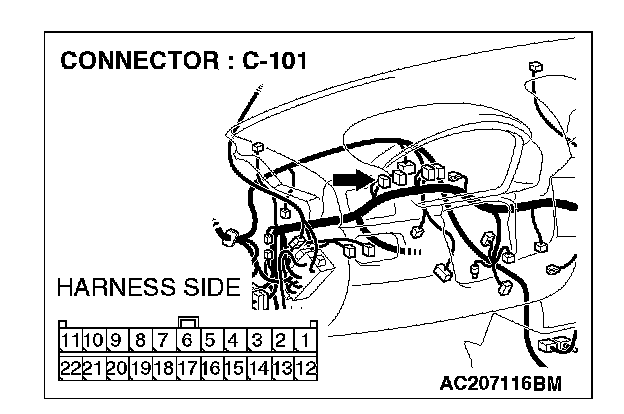
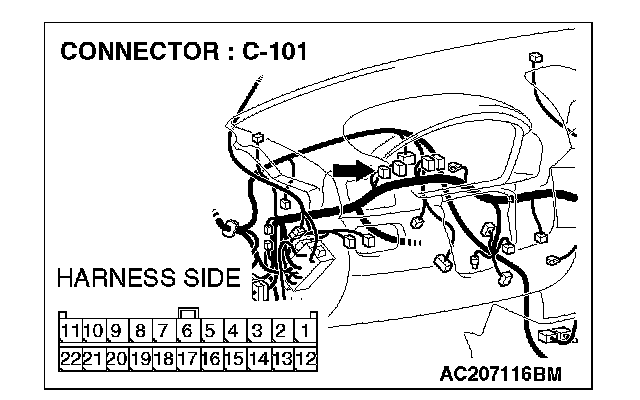
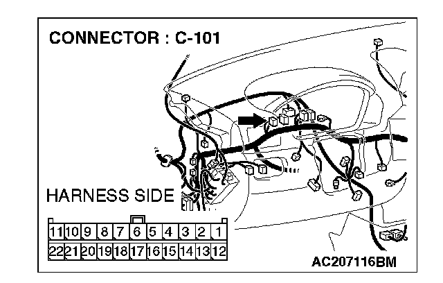
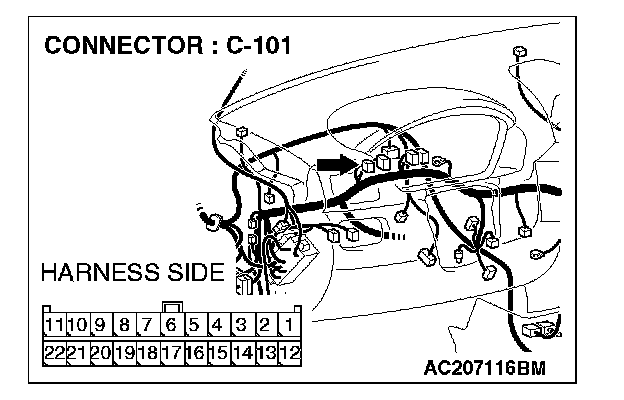
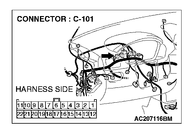
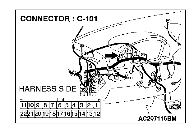
STEP 6. Check joint connector (4) C-101 for loose, corroded or damaged terminals, or terminals pushed back in the connector.
NOTE: For the removal of the joint connector, refer to "How To Disconnect Joint Connector".
CAUTION: The strand end of the twist wire should be within 10 cm (4 inches) from the connector.
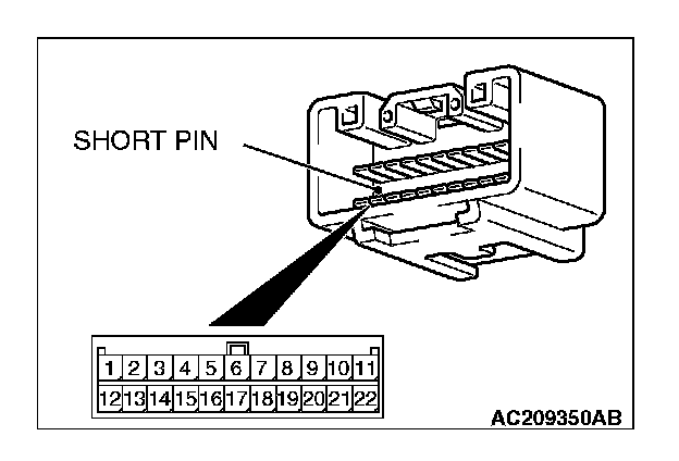
Check the joint connector at the wiring harness side for loose, corroded or damaged terminals, or terminals pushed back in the connector, and also check the short pin behind the connector for corrosion, deformation and delamination.
Q: Is joint connector (4) C-101 in good condition?
YES: Go to Step 7.
NO: Repair the damaged parts. Replace the joint connector as necessary.
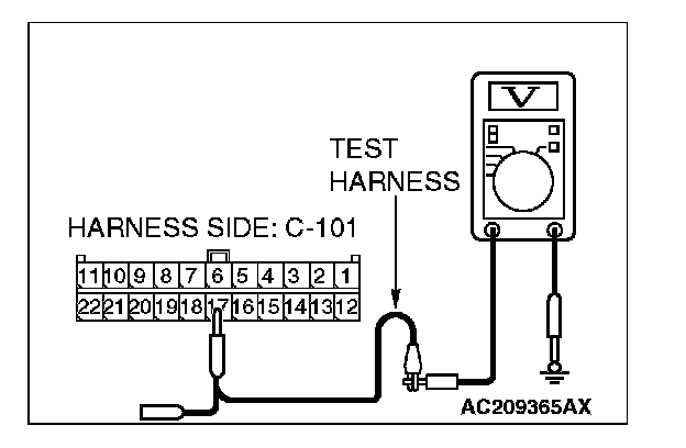
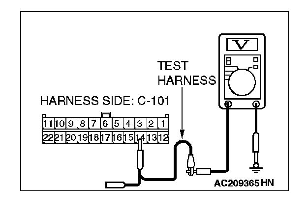
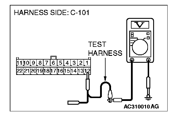
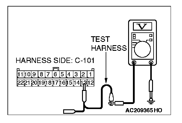
STEP 7. Check the CAN_H line (communication line including the combination meter) between joint connector (4) and the combination meter for a short to the power supply. Measure the voltage at joint connector (4) C-101.
CAUTION:
- A digital multimeter should be used.
- The test wiring harness should be used.
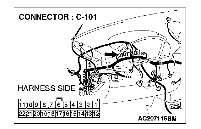
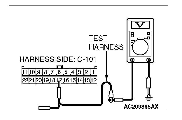
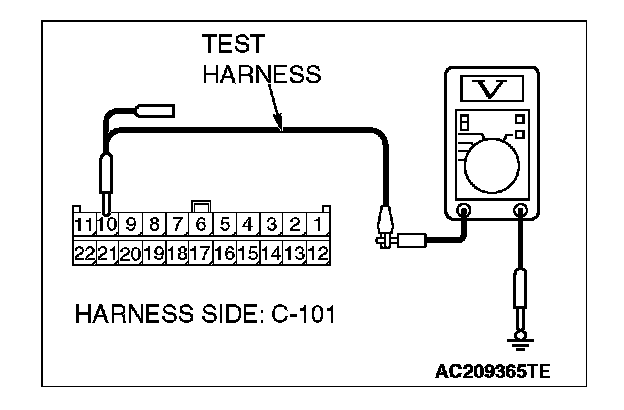
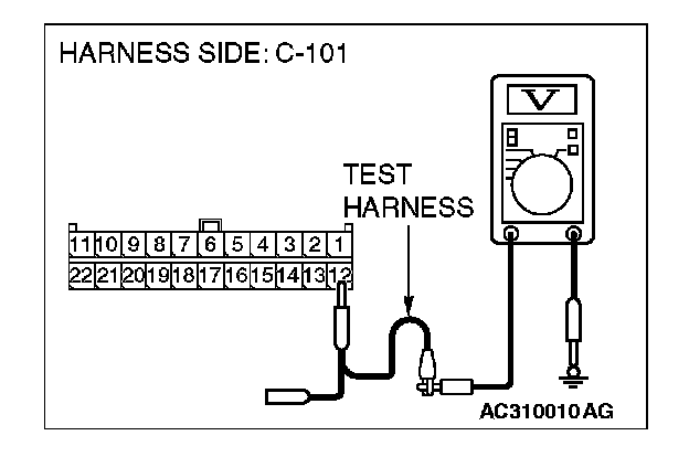
1. Disconnect joint connector (4) C-101, and measure the voltage at the wiring harness side of joint connector (4) C-101.
2. Turn the ignition switch to the "ON" position.
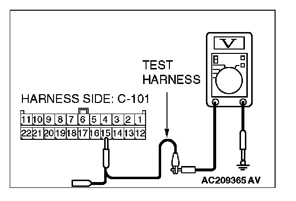
3. Measure the voltage between joint connector (4) terminal 15 and body ground.
OK: 4.0 V or less
Q: Does the voltage measure 4.0 V or less?
YES:
NO:
STEP 8. Check the CAN_H line (communication line only) between joint connector (4) and the combination meter connector for a short to the power supply. Measure the voltage at joint connector (4) C-101.
CAUTION:
- A digital multimeter should be used.
- The test wiring harness should be used.
1. Disconnect joint connector (4) C-101 and combination meter connector C-102, and measure the voltage at the wiring harness side of joint connector (4) C-101.
2. Turn the ignition switch to the "ON" position.
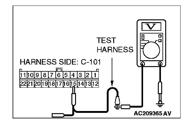
3. Measure the voltage between joint connector (4) terminal 15 and body ground.
OK: 1.0 V or less
CAUTION: Strictly observe the specified wiring harness repair procedure.
Q: Does the voltage measure 1.0 V or less?
YES:
NO:
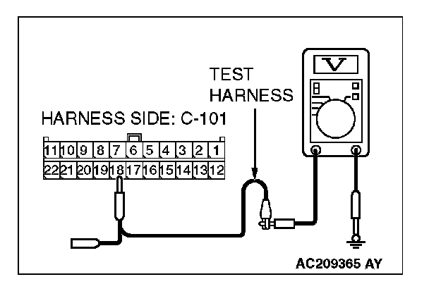
STEP 9. Check the CAN_H line (communication line including the ETACS-ECU) between joint connector (4) and the ETACS-ECU connector for a short to the power supply.Measure the voltage at joint connector (4) C-101.
CAUTION:
- A digital multimeter should be used.
- The test wiring harness should be used.
1. Disconnect joint connector (4) C-101, and measure the voltage at the wiring harness side of joint connector (4) C-101.
2. Turn the ignition switch to the "ON" position.
3. Measure the voltage between joint connector (4) terminal 17 and body ground.
OK: 4.0 V or less
Q: Does the voltage measure 4.0 V or less?
YES:
NO:
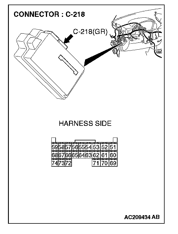
STEP 10. Check ETACS-ECU connector C-218 for loose, corroded or damaged terminals, or terminals pushed back in the connector.
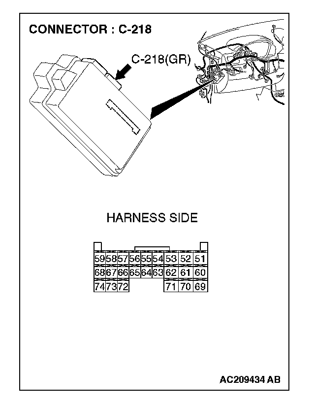
CAUTION: The strand end of the twist wire should be within 10 cm (4 inches) from the connector.
Q: Is ETACS-ECU connector C-218 in good condition?
YES: Go to Step 11.
NO: Repair the damaged parts.
STEP 11. Check the CAN_H line (communication line only) between joint connector (4) and ETACS-ECU connector for a short to the power supply. Measure the voltage at joint connector (4) C-101.
CAUTION:
- A digital multimeter should be used.
- The test wiring harness should be used.
1. Disconnect joint connector (4) C-101 and ETACS-ECU connector C-218, and measure the voltage at the wiring harness side of joint connector (4) C-101.
2. Turn the ignition switch to the "ON" position.
3. Measure the voltage between joint connector (4) terminal 17 and body ground.
OK: 1.0 V or less
CAUTION: Strictly observe the specified wiring harness repair procedure.
Q: Does the voltage measure 1.0 V or less?
YES:
NO:
STEP 12. Check the CAN_H line (communication line including the A/C-ECU) between joint connector (4) and the A/C-ECU connector for a short to the power supply.Measure the voltage at joint connector (4) C-101.
CAUTION:
- A digital multimeter should be used.
- The test wiring harness should be used.
1. Disconnect joint connector (4) C-101, and measure the voltage at the wiring harness side of joint connector (4) C-101.
2. Turn the ignition switch to the "ON" position.
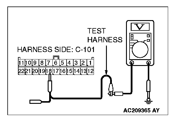
3. Measure the voltage between joint connector (4) terminal 18 and body ground.
OK: 4.0 V or less
Q: Does the voltage measure 4.0 V or less?
YES:
NO:
STEP 13. Check A/C-ECU connector C-42
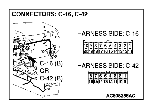
CAUTION: The strand end of the twist wire should be within 10 cm (4 inches) from the connector.
Q: Is A/C-ECU connector C-42
YES: Go to Step 14 .
NO: Repair the damaged parts.
STEP 14. Check the CAN_H line (communication line only) between joint connector (4) and A/C-ECU connector for a short to the power supply. Measure the voltage at joint connector (4) C-101.
CAUTION:
- A digital multimeter should be used.
- The test wiring harness should be used.
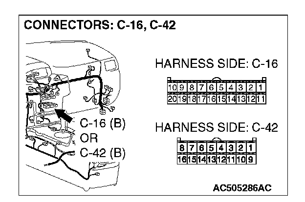
1. Disconnect joint connector (4) C-101 and A/C-ECU connector C-42
2. Turn the ignition switch to the "ON" position.
3. Measure the voltage between joint connector (4) terminal 18 and body ground.
OK: 1.0 V or less
CAUTION: Strictly observe the specified wiring harness repair procedure.
Q: Does the voltage measure 1.0 V or less?
YES:
NO:
STEP 15. Check the CAN_H line (communication line including the SRS-ECU) between joint connector (4) and the SRS-ECU connector for a short to the power supply. Measure the voltage at joint connector (4) C-101.
CAUTION:
- A digital multimeter should be used.
- The test wiring harness should be used.

1. Disconnect joint connector (4) C-101, and measure the voltage at the wiring harness side of joint connector (4) C-101.
2. Turn the ignition switch to the "ON" position.
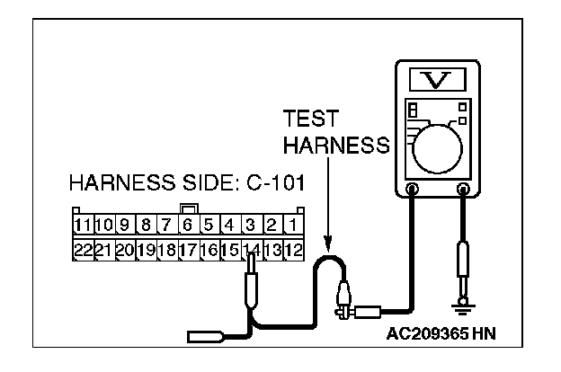
3. Measure the voltage between joint connector (4) terminal 14 and body ground.
OK: 4.0 V or less
Q: Does the voltage measure 4.0 V or less?
YES:
NO:
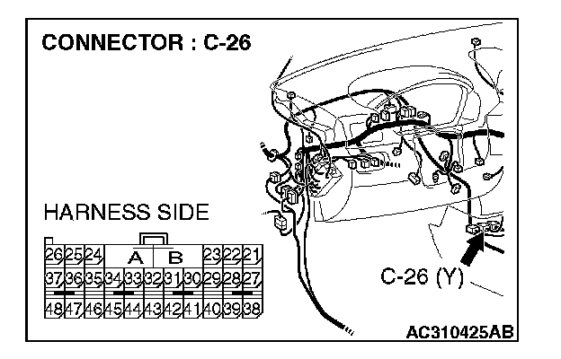
STEP 16. Check SRS-ECU connector C-26 for loose, corroded or damaged terminals, or terminals pushed back in the connector.

CAUTION: The strand end of the twist wire should be within 10 cm (4 inches) from the connector.
Q: Is SRS-ECU connector C-26 in good condition?
YES: Go to Step 17.
NO: Repair the damaged parts.
STEP 17. Check the CAN_H line (communication line only) between joint connector (4) and SRS-ECU connector for a short to the power supply. Measure the voltage at joint connector (4) C-101.
CAUTION:
- A digital multimeter should be used.
- The test wiring harness should be used.
1. Disconnect joint connector (4) C-101 and SRS-ECU connector C-26, and measure the voltage at the wiring harness side of joint connector (4) C-101.
2. Turn the ignition switch to the "ON" position.
3. Measure the voltage between joint connector (4) terminal 14 and body ground.
OK: 1.0 V or less
CAUTION: Strictly observe the specified wiring harness repair procedure.
Q: Does the voltage measure 1.0 V or less?
YES:
NO:
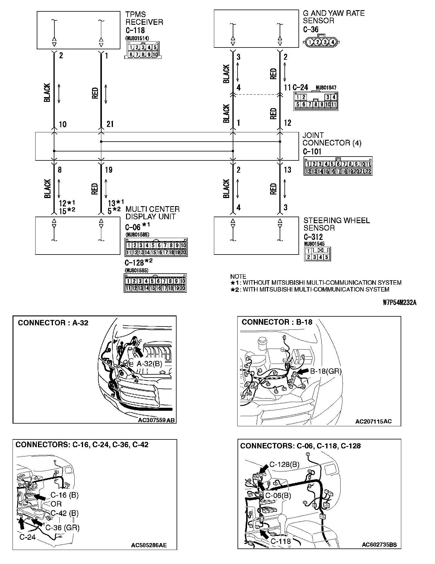
STEP 18. Check the CAN_H line (communication line including the TPMS receiver) between joint connector (4) and the TPMS receiver connector for short to the power supply. Measure the voltage at joint connector (4) C-101.
CAUTION:
- A digital multimeter should be used.
- The test wiring harness should be used.
1. Disconnect joint connector (4) C-101, and measure the voltage at the wiring harness side of joint connector (4) C-101.
2. Turn the ignition switch to the "ON" position.
3. Measure the voltage between joint connector (4) terminal 10 and body ground.
OK: 4.0 V or less
Q: Does the voltage measure 4.0 V or less?
YES: If the voltage measures 4.0 V or less, go to Step 21.
NO: If the voltage measures more than 4.0 V, go to Step 19.
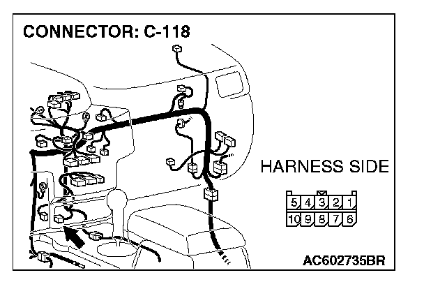
STEP 19. Check TPMS receiver connector C-118 for loose, corroded or damaged terminals, or terminals pushed back in the connector.
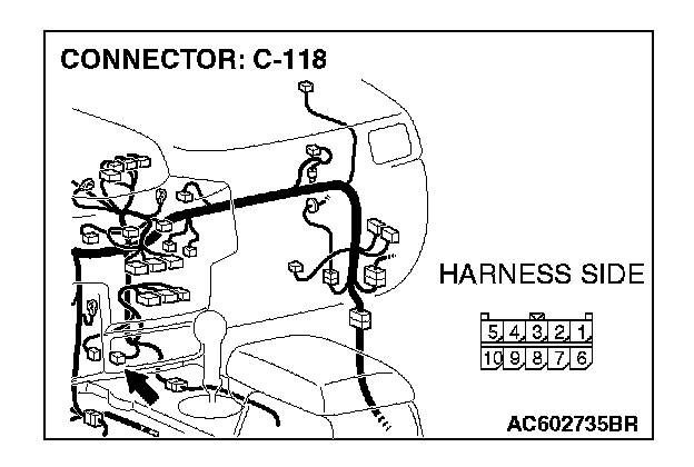
CAUTION: The strand end of the twisted wire should be within 10 cm (4 inches) from the connector.
Q: Is TPMS receiver connector C-118 in good condition?
YES: Go to Step 20.
NO: Repair the damaged parts.
STEP 20. Check the CAN_H line (communication line only) between joint connector (4) and TPMS receiver connector for a short to the power supply. Measure the voltage at joint connector (4) C-101.
CAUTION:
- A digital multimeter should be used.
- The test wiring harness should be used.
1. Disconnect joint connector (4) C-101 and TPMS receiver connector C-118, and measure the voltage at the male side of joint connector (4) C-101.
2. Turn the ignition switch to the "ON" position.

3. Measure the voltage between joint connector (4) terminal 10 and body ground.
OK: 1.0 V or less
CAUTION: Strictly observe the specified wiring harness repair procedure.
Q: Does the voltage measure 1.0 V or less?
YES: If the voltage measures 1.0 V or less, diagnose CAN bus lines thoroughly by referring to Diagnostic Item 9. Diagnostic Item 9
NO: If the voltage measures more than 1.0 V, repair the wiring harness between joint connector (4) and the TPMS receiver connector.
STEP 21. Check the CAN_H line (communication line including the G and yaw rate sensor) between joint connector (4) and G and yaw rate sensor connector for a short to the power supply. Measure the voltage at joint connector (4) C-101.
CAUTION:
- A digital multimeter should be used.
- The test wiring harness should be used.
1. Disconnect joint connector (4) C-101, and measure the voltage at the wiring harness side of joint connector (4) C-101.
2. Turn the ignition switch to the "ON" position.
3. Measure the voltage between joint connector (4) terminal 12 and body ground.
OK: 4.0 V or less
Q: Does the voltage measure 4.0 V or less?
YES:
NO:
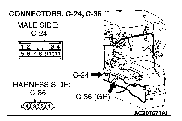
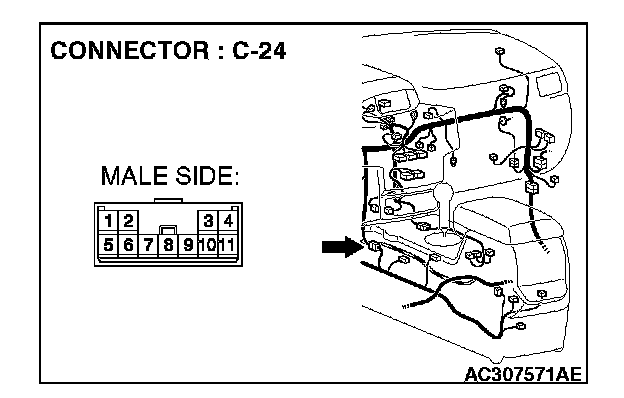
STEP 22. Check G and yaw rate sensor connector C-36 and intermediate connector C-24 for loose, corroded or damaged terminals, or terminals pushed back in the connector.
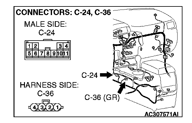
CAUTION: The strand end of the twist wire should be within 10 cm (4 inches) from the connector.
Q: Are G and yaw rate sensor connector C-36 and intermediate connector C-24 in good condition?
YES: Go to Step 23.
NO: Repair the damaged parts.
STEP 23. Check the CAN_H line (communication line only) between intermediate connector C-24 and G and yaw rate sensor connector for a short to the power supply. Measure the voltage at intermediate connector C-24.
CAUTION:
- A digital multimeter should be used.
- The test wiring harness should be used.
1. Disconnect intermediate connector C-24 and G and yaw rate sensor connector C-36, and measure the voltage at the wiring harness side of intermediate connector male side (at front wiring harness side).
2. Turn the ignition switch to the "ON" position.
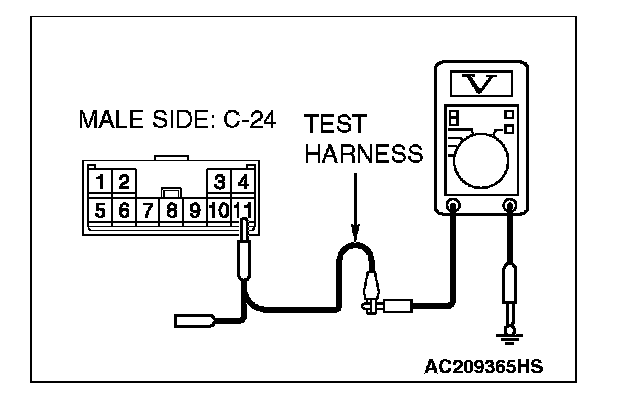
3. Measure the voltage between intermediate connector terminal 11 and body ground.
OK: 1.0 V or less
CAUTION: Strictly observe the specified wiring harness repair procedure.
Q: Does the voltage measure 1.0 V or less?
YES:
NO:
STEP 24. Check the CAN_H line (communication line only) between intermediate connector C-24 and joint connector(4) for a short to the power supply. Measure the voltage at joint connector (4) C-101.
CAUTION:
- A digital multimeter should be used.
- The test wiring harness should be used.
1. Disconnect intermediate connector C-24 and joint connector (4) C-101, and measure the voltage at the wiring harness side of joint connector (4) C-101.
2. Turn the ignition switch to the "ON" position.
3. Measure the voltage between joint connector (4) terminal 12 and body ground.
OK: 1.0 V or less
CAUTION: Strictly observe the specified wiring harness repair procedure.
Q: Does the voltage measure 1.0 V or less?
YES:
NO:
STEP 25. Check the CAN_H line (communication line including the steering wheel sensor) between joint connector (4) and steering wheel sensor connector for a short to the power supply. Measure the voltage at joint connector (4) C-101.
CAUTION:
- A digital multimeter should be used.
- The test wiring harness should be used.
1. Disconnect joint connector (4) C-101, and measure the voltage at the wiring harness side of joint connector (4) C-101.
2. Turn the ignition switch to the "ON" position.
3. Measure the voltage between joint connector (4) terminal 13 and body ground.
OK: 4.0 V or less
Q: Does the voltage measure 4.0 V or less?
YES:
NO:
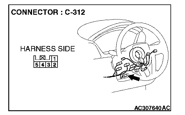
STEP 26. Check steering wheel sensor connector C-312 for loose, corroded or damaged terminals, or terminals pushed back in the connector.
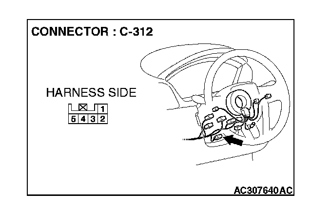
CAUTION: The strand end of the twist wire should be within 10 cm (4 inches) from the connector.
Q: Is steering wheel sensor connector C-312 in good condition?
YES: Go to Step 27.
NO: Repair the damaged parts.
STEP 27. Check the CAN_H line (communication line only) between joint connector (4) and steering wheel sensor connector for a short to the power supply. Measure the voltage at joint connector (4) C-101.
CAUTION:
- A digital multimeter should be used.
- The test wiring harness should be used.
1. Disconnect joint connector (4) C-101 and steering wheel sensor connector C-312, and measure the voltage at the wiring harness side of joint connector (4) C-101.
2. Turn the ignition switch to the "ON" position.
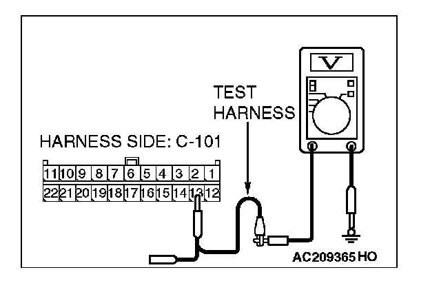
3. Measure the voltage between joint connector (4) terminal 13 and body ground.
OK: 1.0 V or less
CAUTION: Strictly observe the specified wiring harness repair procedure.
Q: Does the voltage measure 1.0 V or less?
YES:
NO:
STEP 28. Check the CAN_H line (communication line including the multi-center display unit (middle-grade type or vehicles with Mitsubishi multi communication system)) between joint connector (4) and multi-center display connector for a short to the power supply. Measure the voltage at joint connector (4) C-101.
CAUTION:
- A digital multimeter should be used.
- The test wiring harness should be used.

1. Disconnect joint connector (4) C-101, and measure the voltage at the wiring harness side of joint connector (4) C-101.
2. Turn the ignition switch to the "ON" position.
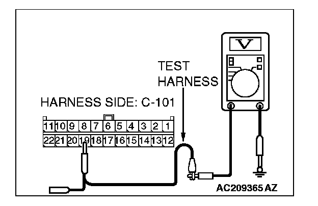
3. Measure the voltage between joint connector (4) terminal 19 and body ground.
OK: 4.0 V or less
Q: Does the voltage measure 4.0 V or less?
YES:
NO: