Part 3
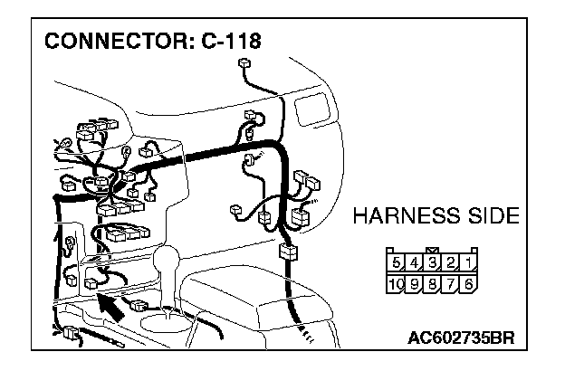
STEP 52. Check TPMS receiver connector C-118 for loose, corroded or damaged terminals, or terminals pushed back in the connector.
CAUTION: The strand end of the twisted wire should be within 10 cm (4 inches) from the connector.
Q: Is TPMS receiver connector C-118 in good condition?
YES: Go to Step 53.
NO: Repair the damaged parts.
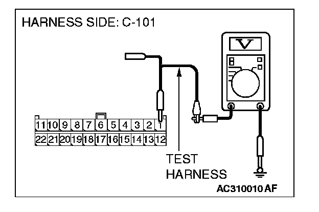
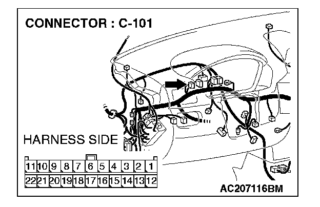
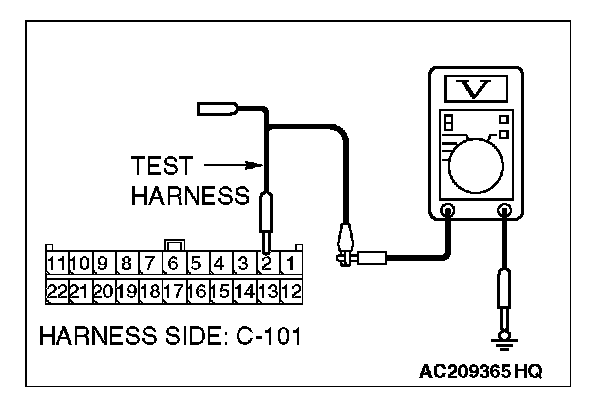
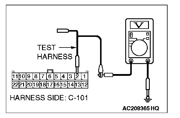
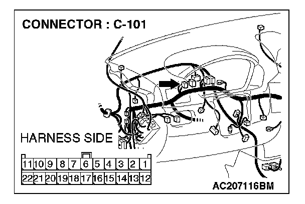
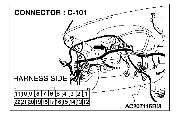
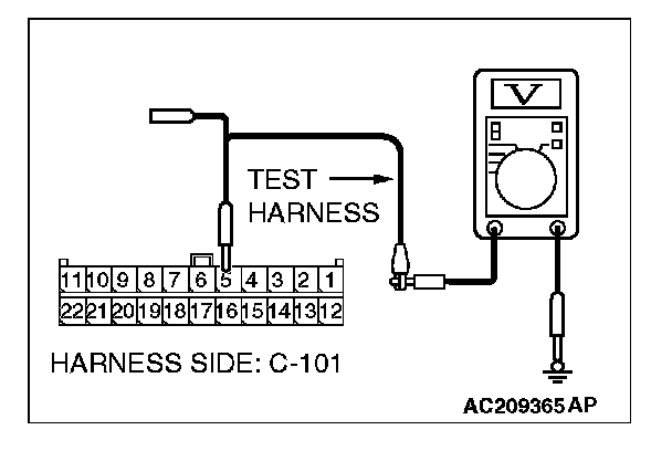
STEP 53. Check the CAN_L line (communication line only) between joint connector (4) and TPMS receiver connector for a short to the power supply. Measure the voltage at joint connector (4) C-101.
CAUTION:
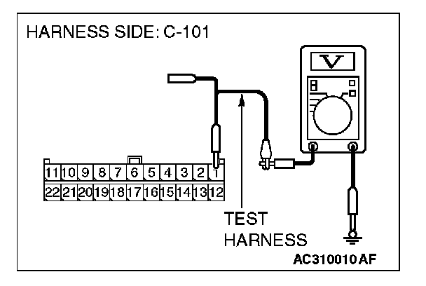
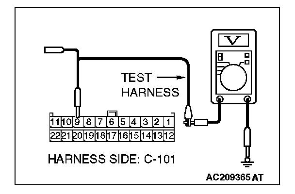
- A digital multimeter should be used.
- The test wiring harness should be used.
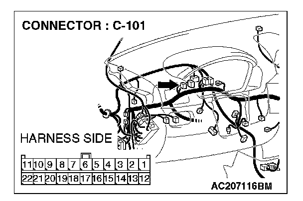
1. Disconnect joint connector (4) C-101 and TPMS receiver connector C-118, and measure the voltage at the male side of joint connector (4) C-101.
2. Turn the ignition switch to the "ON" position.
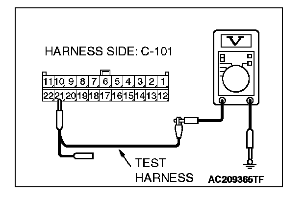
3. Measure the voltage between joint connector (4) terminals 21 and body ground.
OK: 1.0 V or less
CAUTION: Strictly observe the specified wiring harness repair procedure.
Q: Does the voltage measure 1.0 V or less?
YES: If the voltage measures 1.0 V or less, diagnose CAN bus lines thoroughly by referring to Diagnostic Item 9. Diagnostic Item 9
NO: joint connector (4) and the TPMS receiver connector.
STEP 54. Check the CAN_L line (communication line including the G and yaw rate sensor) between joint connector (4) and G and yaw rate sensor connector for a short to the power supply. Measure the voltage at joint connector (4) C-101.
CAUTION:
- A digital multimeter should be used.
- The test wiring harness should be used.
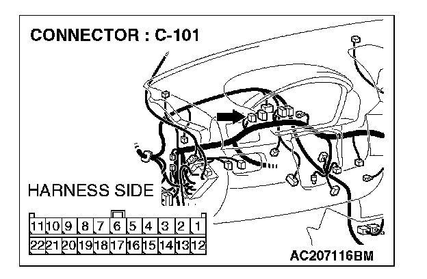
1. Disconnect joint connector (4) C-101, and measure the voltage at the wiring harness side of joint connector (4) C-101.
2. Turn the ignition switch to the "ON" position.
3. Measure the voltage between joint connector (4) terminal 1 and body ground.
OK: 4.0 V or less
Q: Does the voltage measure 4.0 V or less?
YES:
NO:
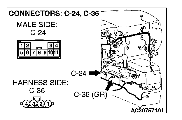
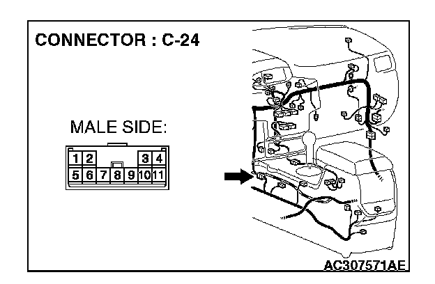
STEP 55. Check G and yaw rate sensor connector C-36 and intermediate connector C-24 for loose, corroded or damaged terminals, or terminals pushed back in the connector.
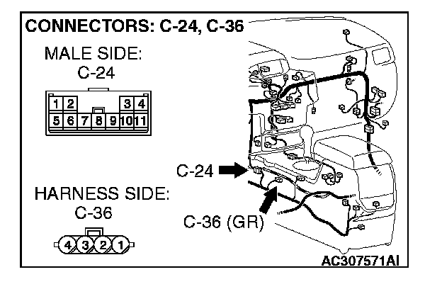
CAUTION: The strand end of the twist wire should be within 10 cm (4 inches) from the connector.
Q: Are G and yaw rate sensor connector C-36 and intermediate connector C-24 in good condition?
YES: Go to Step 56.
NO: Repair the damaged parts.
STEP 56. Check the CAN_L line (communication line only) between intermediate connector C-24 and G and yaw rate sensor connector for a short to the power supply. Measure the voltage at intermediate connector C-24.
CAUTION:
- A digital multimeter should be used.
- The test wiring harness should be used.
1. Disconnect intermediate connector C-24 and G and yaw rate sensor connector C-36, and measure the voltage at the wiring harness side of intermediate connector male side (at front wiring harness side).
2. Turn the ignition switch to the "ON" position.
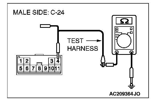
3. Measure the voltage between intermediate connector terminal 4 and body ground.
OK: 1.0 V or less
CAUTION: Strictly observe the specified wiring harness repair procedure.
Q: Does the voltage measure 1.0 V or less?
YES:
NO:
STEP 57. Check the CAN_L line (communication line only) between intermediate connector C-24 and joint connector (4) for a short to the power supply. Measure the voltage at joint connector (4) C-101.
CAUTION:
- A digital multimeter should be used.
- The test wiring harness should be used.
1. Disconnect intermediate connector C-24 and joint connector (4) C-101, and measure the voltage at the wiring harness side of joint connector (4) C-101.
2. Turn the ignition switch to the "ON" position.
3. Measure the voltage between joint connector (4) terminal 1 and body ground.
OK: 1.0 V or less
CAUTION: Strictly observe the specified wiring harness repair procedure.
Q: Does the voltage measure 1.0 V or less?
YES:
NO:
STEP 58. Check the CAN_L line (communication line including the steering wheel sensor) between joint connector (4) and steering wheel sensor connector for a short to the power supply. Measure the voltage at joint connector (4) C-101.
CAUTION:
- A digital multimeter should be used.
- The test wiring harness should be used.
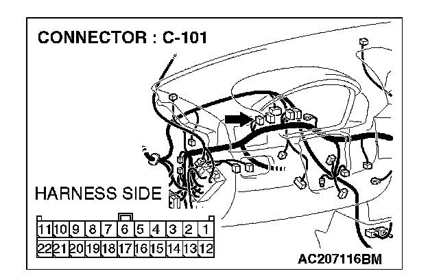
1. Disconnect joint connector (4) C-101, and measure the voltage at the wiring harness side of joint connector (4) C-101.
2. Turn the ignition switch to the "ON" position.
3. Measure the voltage between joint connector (4) terminal 2 and body ground.
OK: 4.0 V or less
Q: Does the voltage measure 4.0 V or less?
YES:
NO:
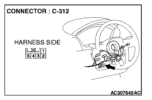
STEP 59. Check steering wheel sensor connector C-312 for loose, corroded or damaged terminals, or terminals pushed back in the connector.
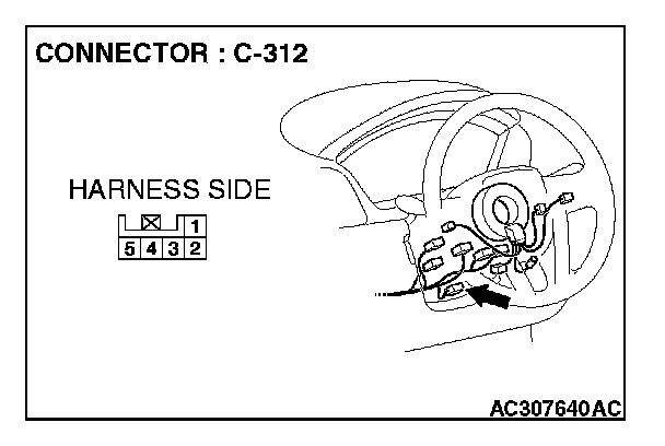
CAUTION: The strand end of the twist wire should be within 10 cm (4 inches) from the connector.
Q: Is steering wheel sensor connector C-312 in good condition?
YES: Go to Step 60.
NO: Repair the damaged parts.
STEP 60. Check the CAN_L line (communication line only) between joint connector (4) and steering wheel sensor connector for a short to the power supply. Measure the voltage at joint connector (4) C-101.
CAUTION:
- A digital multimeter should be used.
- The test wiring harness should be used.
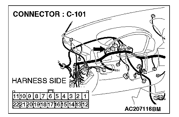
1. Disconnect joint connector (4) C-101 and steering wheel sensor connector C-312, and measure the voltage at the wiring harness side of joint connector (4) C-101.
2. Turn the ignition switch to the "ON" position.
3. Measure the voltage between joint connector (4) terminal 2 and body ground.
OK: 1.0 V or less
CAUTION: Strictly observe the specified wiring harness repair procedure.
Q: Does the voltage measure 1.0 V or less?
YES:
NO:
STEP 61. Check the CAN_L line (communication line including the multi-center display unit (middle-grade type or vehicles with Mitsubishi multi communication system) ) between joint connector (4) and multi-center display connector for a short to the power supply. Measure the voltage at joint connector (4) C-101.
CAUTION:
- A digital multimeter should be used.
- The test wiring harness should be used.
1. Disconnect joint connector (4) C-101, and measure the voltage at the wiring harness side of joint connector (4) C-101.
2. Turn the ignition switch to the "ON" position.
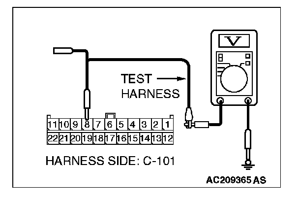
3. Measure the voltage between joint connector (4) terminal 8 and body ground.
OK: 4.0 V or less
Q: Does the voltage measure 4.0 V or less?
YES:
NO:
STEP 62. Check multi-center display unit (middle-grade type or vehicles with Mitsubishi multi communication system) connector C-06
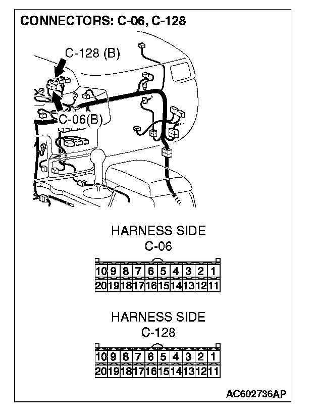
CAUTION: The strand end of the twist wire should be within 10 cm (4 inches) from the connector.
Q: Is multi-center display unit (middle-grade type or vehicles with Mitsubishi multi communication system) connector C-06
YES: Go to Step 63.
NO: Repair the damaged parts.
STEP 63. Check the CAN_L line (communication line only) between joint connector (4) and multi-center display unit(middle-grade type or vehicles with Mitsubishi multicommunication system) connector for a short to the power supply. Measure the voltage at joint connector (4) C-101.
CAUTION:
- A digital multimeter should be used.
- The test wiring harness should be used.
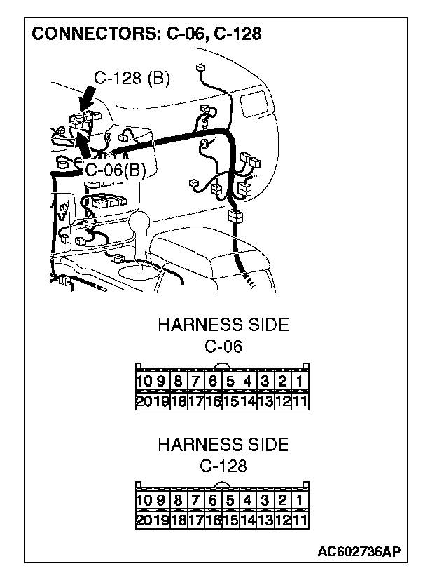
1. Disconnect joint connector (4) C-101 and multi-center display unit (middle-grade type or vehicles with Mitsubishi multi communication system) connector C-06
2. Turn the ignition switch to the "ON" position.

3. Measure the voltage between joint connector (4) terminal 8 and body ground.
OK: 1.0 V or less
CAUTION: Strictly observe the specified wiring harness repair procedure.
Q: Does the voltage measure 1.0 V or less?
YES:
NO:
STEP 64. Check the CAN_L line (communication line only) between joint connector (4) and the data link connector for a short to the power supply. Measure the voltage at joint connector (4) C-101.
CAUTION:
- A digital multimeter should be used.
- The test wiring harness should be used.
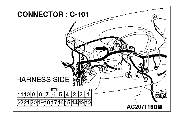
1. Disconnect joint connector (4) C-101, and measure the voltage at the wiring harness side of joint connector (4) C-101.
2. Turn the ignition switch to the "ON" position.
3. Measure the voltage between joint connector (4) terminal 5 and body ground.
OK: 1.0 V or less
CAUTION: Strictly observe the specified wiring harness repair procedure.
Q: Does the voltage measure 1.0 V or less?
YES:
NO:
STEP 65. Check the CAN_L line (communication line only) between intermediate connector C-31 and joint connector (4) for a short to the power supply. Measure the voltage at joint connector (4) C-101.
CAUTION:
- A digital multimeter should be used.
- The test wiring harness should be used.
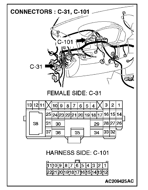
1. Disconnect intermediate connector C-31 and joint connector (4) C-101, and measure the voltage at the wiring harness side of joint connector (4) C-101.
2. Turn the ignition switch to the "ON" position.
3. Measure the voltage between joint connector (4) terminal 9 and body ground.
OK: 1.0 V or less
CAUTION: Strictly observe the specified wiring harness repair procedure.
Q: Does the voltage measure 1.0 V or less?
YES:
NO:
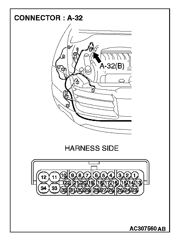
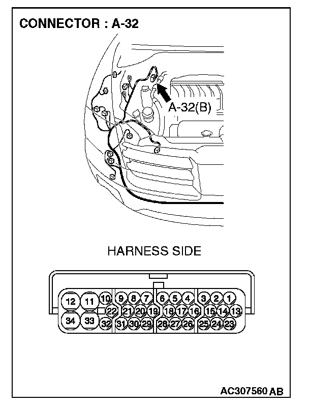
STEP 66. Check ASC/TCL-ECU connector A-32 for loose, corroded or damaged terminals, or terminals pushed back in the connector.
CAUTION: The strand end of the twist wire should be within 10 cm (4 inches) from the connector.
Q: Is ASC/TCL-ECU connector A-32 in good condition?
YES: Go to Step 67.
NO: Repair the damaged parts.
STEP 67. Check the CAN_L line (communication line only) between intermediate connector C-31 and ASC/TCL-ECU connector for a short to the power supply. Measure, the voltage at intermediate connector C-31.
CAUTION:
- A digital multimeter should be used.
- The test wiring harness should be used.
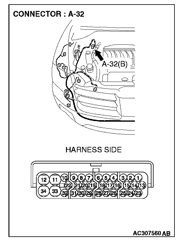
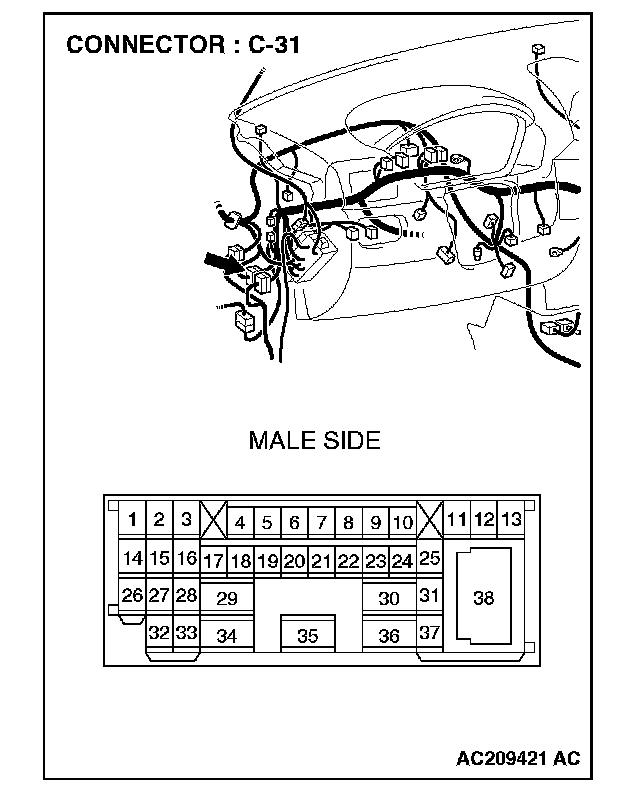
1. Disconnect intermediate connector C-31 and ASC/TCL-ECU connector A-32, and measure the voltage at the male side of intermediate connector C-31 (at front wiring harness side).
2. Turn the ignition switch to the "ON" position.
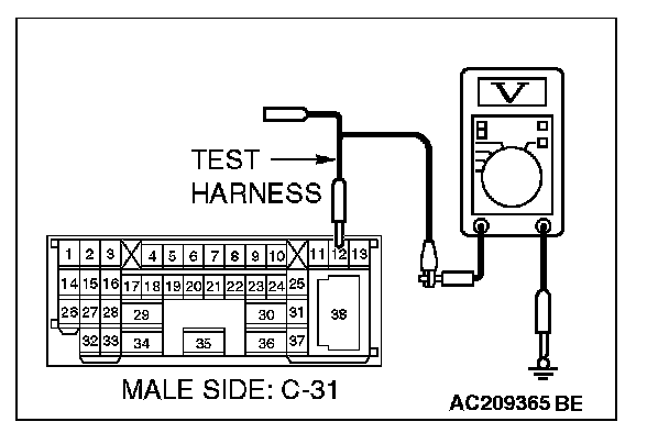
3. Measure the voltage between intermediate connector terminal 12 and body ground.
OK: 1.0 V or less
CAUTION: Strictly observe the specified wiring harness repair procedure.
Q: Does the voltage measure 1.0 V or less?
YES:
NO:
STEP 68. Check the CAN_L line (communication line only) between the powertrain control module connector and ASC/TCL-ECU connector for a short to the power supply. Measure voltage at powertrain control module connector B-18.
CAUTION:
- A digital multimeter should be used.
- The test wiring harness should be used.
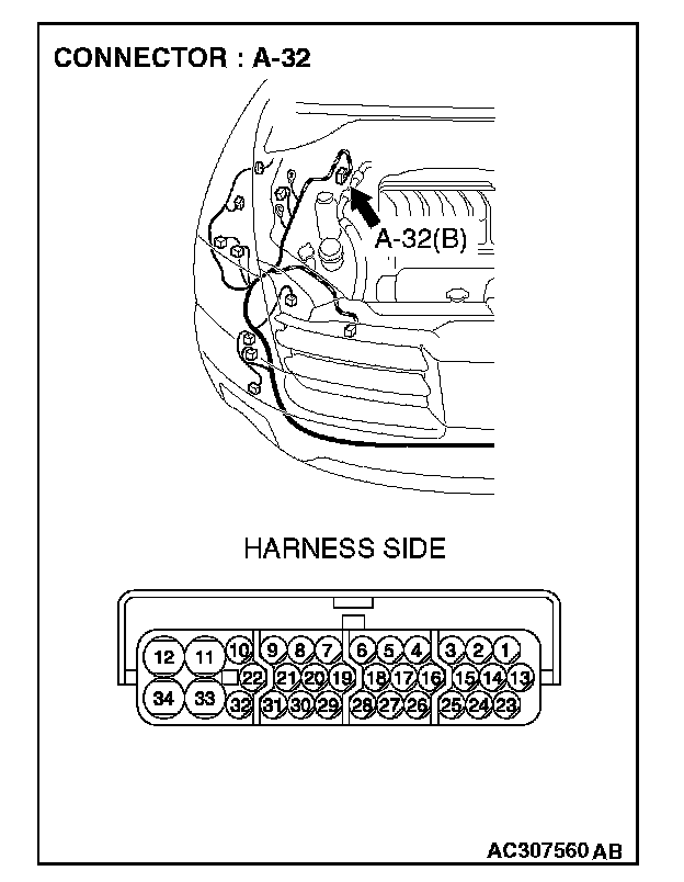
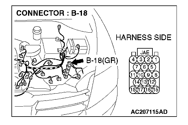
1. Disconnect powertrain control module connector B-18 and ASC/TCL-ECU connector A-32, and measure the voltage at the harness side of powertrain control module connector B-18.
2. Turn the ignition switch to the "ON" position.
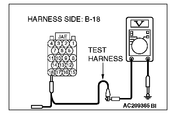
3. Measure the voltage between powertrain control module connector terminal 18 and body ground.
OK: 1.0 V or less
CAUTION: Strictly observe the specified wiring harness repair procedure.
Q: Does the voltage measure 1.0 V or less?
YES:
NO:
STEP 69. Check the CAN_L line inside the ASC/TCL-ECU for a short to the power supply. Measure the voltage at ASC/TCL-ECU connector A-32 for loose, corroded or damaged terminals, or terminals pushed back in the connector.
CAUTION:
- A digital multimeter should be used.
- The test wiring harness should be used.
1. Disconnect ASC/TCL-ECU connector A-32.
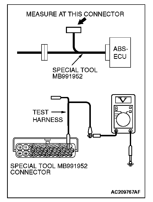
2. Connect special tool MB991952 (ABS check harness) to the ASC/TCL-ECU and the wiring harness, and measure the voltage at special tool MB991952 (ABS check harness).
3. Turn the ignition switch to the "ON" position.
4. Measure the voltage between special tool MB991952 (ABS check harness) connector terminal 14 and body ground.
OK: 4.0 V or less
Q: Does the voltage measure 4.0 V or less?
YES:
NO: